


Getting Started Teledyne API – Model T700 Dynamic Dilution Calibrator
62
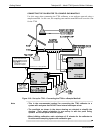
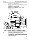
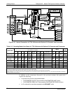
CALIBRATION MANIFOLD EXHAUST/VENT LINE
The manifold’s excess gas should be vented outside of the room. This vent should be of
large enough internal diameter to avoid any appreciable pressure drop, and it must be
located sufficiently downstream of the output ports to assure that no ambient air enters
the manifold due to eddy currents or back diffusion.
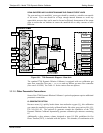
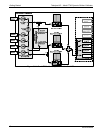
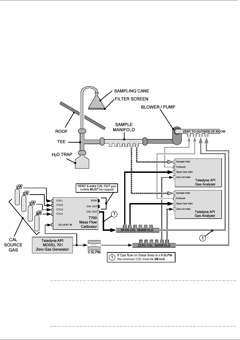
CONNECTING THE CALIBRATOR TO A DUAL SPAN GAS / ZERO AIR
CALIBRATION MANIFOLD
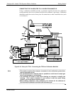
Another type of calibration setup utilizes separate span gas and the zero air manifolds
(see Figure 3-20).
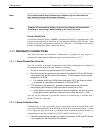
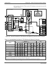
Figure 3-20: Set up for T700 – Connecting the T700 to a Dual Span Gas / Zero Air Manifold
Note
This set up is subject to the same notes and conditions as the single calibration
manifold described previously with the following two exceptions:
• The T700 total gas flow rate (Cal Gas Flow Rate + Diluent Flow Rate) out should
be greater than the Total Flow requirements of the entire system.
• The manifolds as shown in the above drawing are oriented to simplify the
drawing. Their actual orientation in your set-up is with the ports facing upward.
All unused ports must be capped.
06873B DCN6388