


Principles of Operation Teledyne API – Model T700 Dynamic Dilution Calibrator
302
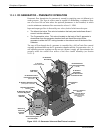
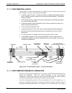
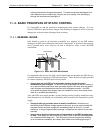
10.7.2. PHOTOMETER LAYOUT
The photometer is where the absorption of UV light by ozone is measured and converted
into a voltage. It consists of several sub-assemblies:
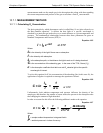
A mercury-vapor UV lamp. This lamp is coated in a material that optically screens
the UV radiation output to remove the O
3
producing 185nm radiation. Only light at
254nm is emitted.
An AC power supply to supply the current for starting and maintaining the plasma
arc of the mercury vapor lamp.
A thermistor and DC heater attached to the UV Lamp to maintain the Lamp at an
optimum operating temperature.
42 cm long quartz absorption tube.
A thermistor attached to the quartz tube for measuring sample gas temperature.
Gas inlet and outlet mounting blocks that route sample gas into and out of the
photometer.
The vacuum diode, UV detector that converts UV light to a DC current.
A preamplifier assembly, which convert the Detector’s current output into a DC
Voltage then amplifies it to a level readable by the A-to-D converter circuitry of the
instrument’s motherboard.
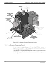
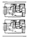
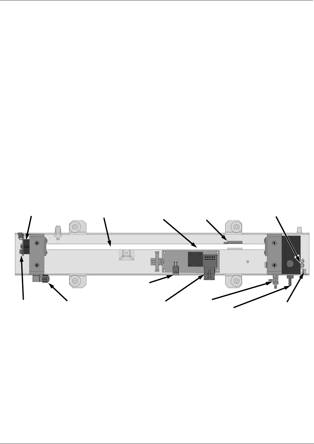
Absorption Tube
UV Lamp Heater
Control PCA
Sample Gas
Outlet
UV Lamp Power
Transformer
Power Connector
from
+15 VDC power supply
UV Lamp Power
Supply
(200 VAC @ 30 kHz)
Sam
p
le Gas Inlet UV Detector
Preamp PCA
UV Detector
Sample Gas
Thermistor
UV Lamp
UV Lamp Thermistor
(UV Lamp Heater Behind Thermistor)
Figure 10-20: O
3
Photometer Layout – Top Cover Removed
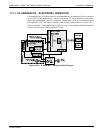
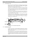
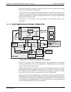
10.7.3. PHOTOMETER PNEUMATIC OPERATION
The flow of gas through the photometer is created by a small internal pump that pulls air
though the instrument. There are several advantages to this “pull through”
configuration. Placing the pump down stream from the absorption tube avoids problems
caused by the pumping process heating and compressing the sample.
In order to measure the presence of low concentrations of O
3
in the sample air, it is
necessary to establish and maintain a relatively constant and stable volumetric flow of
sample gas through the photometer. The simplest way to accomplish this is by placing a
06873B DCN6388