


Teledyne API – Model T700 Dynamic Dilution Calibrator
xix
LIST OF TABLES
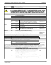
Table 1-1: Analyzer Options....................................................................................................................................24
Table 2-1: T700 Dilution System Specifications......................................................................................................27
Table 2-2: T700 Dilution Electrical and Physical Specifications..............................................................................27
Table 2-3: T700 Specifications for Optional Ozone Generator ...............................................................................28
Table 2-4: T700 Specifications for Optional O
3
Photometer ...................................................................................28
Table 3-1: Display Screen and Touch Control Description .....................................................................................34
Table 3-2: Rear Panel Description ..........................................................................................................................37
Table 3-3: Status Output Pin Assignments .............................................................................................................42
Table 3-4: T700 Control Input Pin Assignments......................................................................................................43
Table 3-5: T700 Control Output Pin Assignments...................................................................................................45
Table 3-6: NIST Standards for CO
2
.........................................................................................................................55
Table 3-7: NIST Standards for CO ..........................................................................................................................56
Table 3-8: NIST Standards for H
2
S .........................................................................................................................56
Table 3-9: NIST Standards for CH
4
.........................................................................................................................56
Table 3-10: NIST Standards for O
2
.........................................................................................................................56
Table 3-11: NIST Standards for SO
2
.......................................................................................................................57
Table 3-12: NIST Standards for NO ........................................................................................................................57
Table 3-13: NIST Standards for Propane (C
3
H
8
).....................................................................................................57
Table 3-14: Operating Mode Valve States for T700 Calibrator with Optional O
3
Generator...................................64
Table 3-15: Operating Mode Valve States for T700 Calibrator with Optional O
3
Generator and Photometer........66
Table 3-16: Possible Warning Messages at Start-Up .............................................................................................78
Table 3-17: T700 Default Gas Types ......................................................................................................................81
Table 3-18: T700 Units of Measure List ..................................................................................................................88
Table 4-1: Calibrator Operating Modes...................................................................................................................97
Table 4-2: Status of Internal Pneumatics During STANDBY Mode ........................................................................98
Table 4-3: Test Functions Defined ....................................................................................................................... 101
Table 4-4: Status of Internal Pneumatics During GENERATE Mode................................................................... 102
Table 4-5: Status of Internal Pneumatics During GENERATE GPT Mode...................................................... 111
Table 4-6: Status of Internal Pneumatics During GENERATE GPTPS Mode................................................. 113
Table 4-7: Internal Pneumatics During Purge Mode ............................................................................................ 116
Table 4-8: Automatic Calibration SEQUENCE Set Up Attributes ........................................................................ 119
Table 4-9: Calibration SEQUENCE Step Instruction............................................................................................ 120
Table 4-10: Sequence Progress Reporting Mode................................................................................................ 130
Table 4-11: Password Levels ............................................................................................................................... 145
Table 4-12: Variable Names (VARS) ................................................................................................................... 148
Table 4-13: DIAG – Analog I/O Functions............................................................................................................ 151
Table 4-14: Test Channels Functions available on the T700’s Analog Output.................................................... 154
Table 4-15: Analog Output Voltage Range Min/Max............................................................................................ 156
Table 4-16: Voltage Tolerances for the TEST CHANNEL Calibration ................................................................. 163
Table 5-1: COMM Port Communication Modes ................................................................................................... 176
Table 5-2: Ethernet Status Indicators................................................................................................................... 181
Table 5-3: LAN/Internet Configuration Properties ................................................................................................ 182
Table 6-1: Terminal Mode Software Commands.................................................................................................. 190
Table 6-2: Teledyne API Serial I/O Command Types .......................................................................................... 192
Table 7-1: Examples of MFC Calibration Points .................................................................................................. 199
Table 7-2: T700 Pressure Sensor Calibration Setup............................................................................................ 218
Table 8-1: T700 Maintenance Schedule .............................................................................................................. 226
Table 9-1: Warning Messages in Front Panel Display Param Field..................................................................... 243
06873B DCN6388