


Calibration and Verification Teledyne API – Model T700 Dynamic Dilution Calibrator
200
7.2.1. SETUP FOR VERIFICATION AND CALIBRATION OF THE T700’S
MFC’S
Note
A separate flow meter is required for the procedure.
1. Turn off the T700 Dynamic Dilution Calibrator.
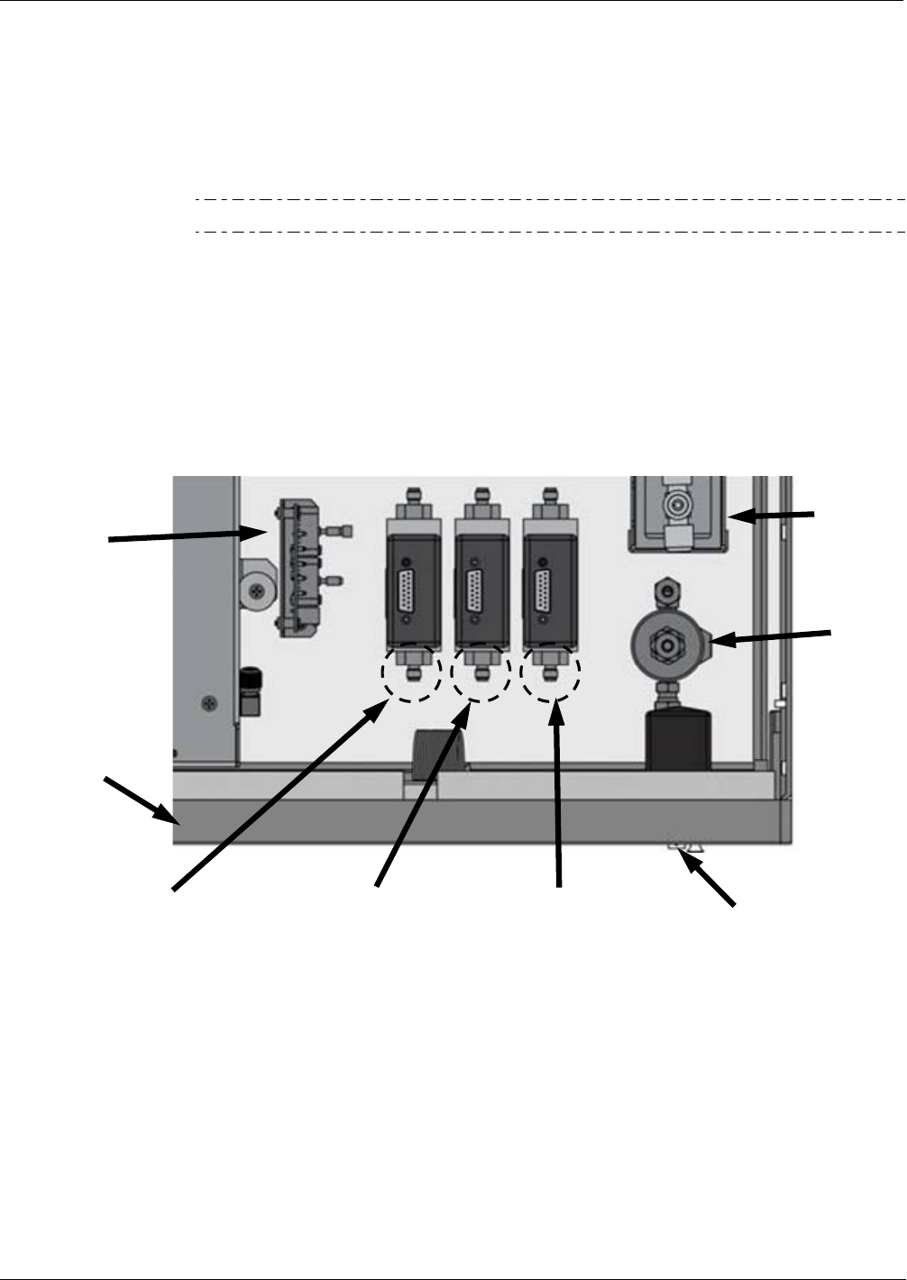
2. Open the front panel to the T700 calibrator. This is the easiest access to the MFC
output ports.
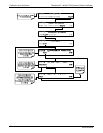
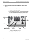
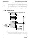
A locking screw located at the top center of the front panel (See Figure 3-1)
must be removed before th
e panel can be opened.
3. Attach the flow meter directly to the output port of the MFC to be checked/tested.
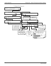
Outlet Port for
Diluent
Mass Flow Controller
Input Gas
Pressure
Sensor
PCA
Outlet Port for
Cal Gas
Mass Flow Controller
ON / OFF
Switch
Front Panel
PHOTOMETER
Outlet Port for
Optional 2nd Cal Gas
Mass Flow Controller
GPT
Valve
GPT
Chamber
Figure 7-1: Location of MFC Outlet Ports
4. Turn the T700 Dynamic Dilution Calibrator ON.
06873B DCN6388