


Teledyne API – Model T700 Dynamic Dilution Calibrator Troubleshooting and Service
251
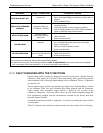
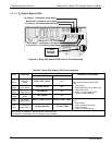
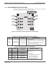
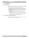
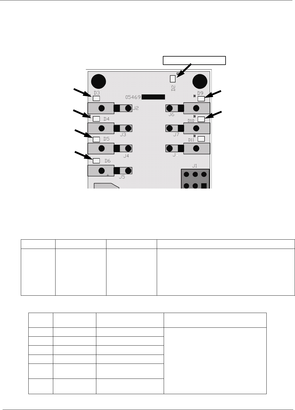
9.3.3. VALVE DRIVER PCA STATUS LEDS
The Signal I/O submenu also includes VARS that can be used to turn the various input
gas valves on and off as part of a diagnostic investigation.
WATCHDOG INDICATOR
CAL GAS
VALVE 1
CAL GAS
VALVE 2
CAL GAS
VALVE 3
CAL GAS
VALVE 4
PURGE
V
ALVE
DILUENT
VALVE
Figure 9-4: Valve Driver PCA Status LEDS Used for Troubleshooting
Table 9-6: Valve Driver Board Watchdog LED Failure Indications
LED Function Fault Status Indicated Failure(s)
D1
(Red)
I
2
C bus Health
(Watchdog Circuit)
Continuously ON
or
Continuously OFF
Failed/Halted CPU
Faulty Mother Board, Valve Driver board or Relay
PCA
Faulty Connectors/Wiring between Mother Board,
Valve Driver board or Relay PCA
Failed/Faulty +5 VDC Power Supply (PS1)
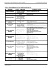
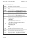
Table 9-7: Relay PCA Status LED Failure Indications
LED FUNCTION
ACTIVATED BY SIGNAL
I/O PARAMETER
DIAGNOSTIC TECHNIQUE
D3
Cal Gas CYL1 CYL_VALVE_1
D4
Cal Gas CYL2 CYL_VALVE_2
D5
Cal Gas CYL3 CYL_VALVE_3
D6
Cal Gas CYL4 CYL_VALVE_4
D9
Purge Valve
Status
PURGE_VALVE
D10
Diluent Valve
Status
INPUT_VALVE
Valve should audibly change states and
LED should glow.
If not:
Failed Valve
Failed Valve Driver IC on Relay PCA
Failed Valve Driver Board
Faulty +12 VDC Supply (PS2)
Faulty Connectors/Wiring
06873B DCN6388