


Teledyne API – Model T700 Dynamic Dilution Calibrator Calibration and Verification
219
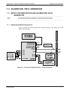
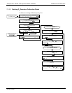
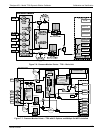
Figure 7-6: Pressure Monitor Points – T700 – Basic Unit
DILUENT
PRESSURE
SENSOR
CAL GAS
PRESSURE
SENSOR
PHOTOMETER
PRESSURE SENSOR
O
3
GEN / PHOTOMETER
PRESSURE / FLOW SENSOR PCA
O
3
GAS INPUT
PRESSURE SENSOR
Flow Control
(1.0 LPM)
On Back Panel
Instrument Chassis
GAS OUTPUT MANIFOLD
PHOTOMETER
OUTLET
CAL GAS
OUTPUT 2
VENT
CAL GAS
OUTPUT 1
DILUENT
INLET
GAS INPUT MANIFOLD
(on back panel)
Purge
Valve
CAL GAS 1
INLET
CAL GAS 3
INLET
CAL GAS 4
INLET
CAL GAS 2
INLET
Cal Gas
Mass Flow Controller 1
Diluent
Mass Flow Controller
GPT
Volume
PHOTOMETER
INLET
EXHAUST
PHOTOMETER
ZERO OUT
PHOTOMETER
ZERO IN
PHOTOMETER BENCH
PUMP
Flow Control
(800 cm
3
)
Cal Gas
Mass Flow Controller 2
INTERNAL
VENT
Pressure
Regulator
GPT
Valve
O
3
Gen
Valve
REF/MEAS
Valve
DILUENT
Valve
grn
blk
red
blu
blu
blu
blk
red
gry
gry
wht
vio
vio
wht
grn
brn
brn
brn
orn
yel
orn
yel
yel
yel
yel
yel
Pressure
Monitor
Pressure
Monitor
Pressure
Monitor
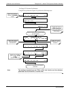
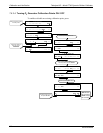
Figure 7-7: Pressure Monitor Points – T700 with O
3
Options and Multiple Cal MFCs Installed
06873B DCN6388