


Teledyne API – Model T700 Dynamic Dilution Calibrator Getting Started
41
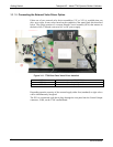
3.3.1.2. Connecting Analog Outputs
The T700 is equipped with an analog output channel accessible through a connector on
the back panel of the instrument. The standard configuration for this output is 0-5 VDC.
It can be set by the user to output one of a variety of diagnostic test functions (see
Section 4.10.1.2).
To access these signals attach a strip chart recorder and/or data-logger to
the appropriate
analog output connections on the rear panel of the calibrator.
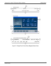
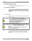
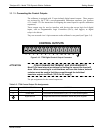
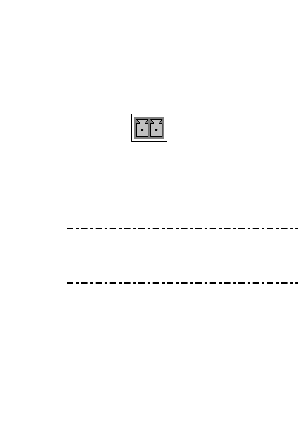
Pin-outs for the analog output connector at the rear panel of the instrument are:
ANALOG OUT
+
–
Figure 3-7: T700 Analog Output Connector
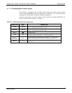
3.3.1.3. Connecting the Status Outputs
The status outputs report calibrator conditions via optically isolated NPN transistors,
which sink up to 50 mA of DC current. These outputs can be used to interface with
devices that accept logic-level digital inputs, such as Programmable Logic Controllers
(PLCs). Each Status bit is an open collector output that can withstand up to 40 VDC.
All of the emitters of these transistors are tied together and available at D.
ATTENTION
COULD DAMAGE INSTRUMENT AND VOID WARRANTY
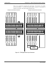
Most PLC’s have internal provisions for limiting the current that the input
will draw from an external device. When connecting to a unit that does
not have this feature, an external dropping resistor must be used to limit
the current through the transistor output to less than 50 mA. At 50 mA, the
transistor will drop approximately 1.2V from its collector to emitter.
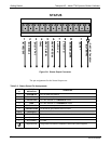
The status outputs are accessed via a 12-pin connector on the calibrator’s rear panel
labeled STATUS. The function of each pin is defined in Table 3-3.
06873B DCN6388