


Getting Started Teledyne API – Model T700 Dynamic Dilution Calibrator
66
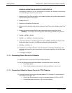
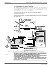
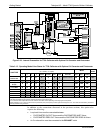
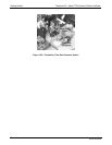
O3 Generator Assembly
On Back Panel
orn
yel
grn
brn
blk
red
blu
blu
blk
red
gry
wht
vio
vio
grn
brn
brn
orn
yel
yel
yel
gry
wht
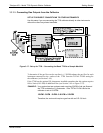
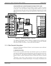
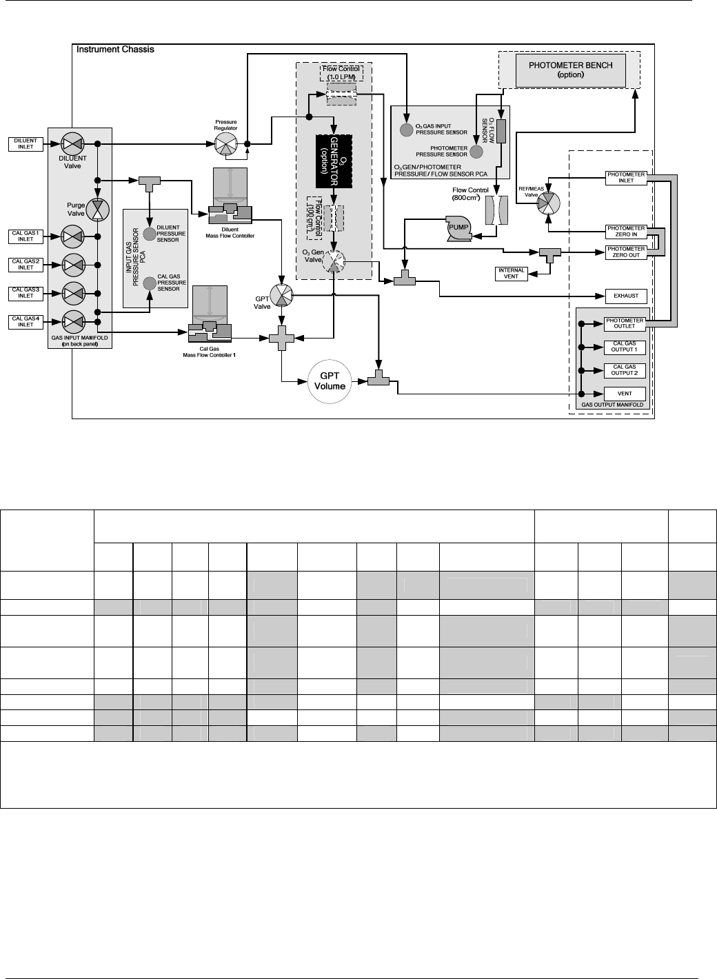
Figure 3-23: Internal Pneumatics for T700 Calibrator with Optional O
3
Generator and Photometer
Table 3-15: Operating Mode Valve States for T700 Calibrator with Optional O
3
Generator and Photometer
VALVES
(X = Closed; O = Open)
MFCs
PHOT
PUMP
GAS TYPE
CYL
1
CYL
2
CYL
3
CYL
4
PURGE DILUENT GPT
O
3
GEN
PHOT M/R
CAL1 CAL2
1
DILUENT
Generate
Source Gas
O
2
O
2
O
2
O
2
X O X X
Reference Phase
ON
3
ON
3
ON OFF
Generate O
3
X
X X X X O X O
Switching
OFF
OFF
OFF ON
4
Leak Check
0-17%
X X X X O O X X
ON ON ON
Leak Check
17%-100%
X X X X O X X X
ON ON ON
GPT
O
2
O
2
O
2
O
2
X O O O
Reference Phase
ON
3
ON
3
ON OFF
GPTPS
X
X X X X O O O
Switching
OFF
OFF
ON ON
4
PURGE
X
X X X O O O O
Reference Phase
ON
3
ON
3
ON OFF
STANDBY
X X X X X O X X
Reference Phase
OFF
OFF
OFF OFF
1
Only present if multiple cal gas MFC option is installed.
2
The valve associated with the cylinder containing the chosen source gas is open.
3
In an instrument with multiple MFCs the CPU chooses which MFC to use depending on the target gas flow requested.
4
When generating O
3
or in GPT Pre-Set mode, the photometer pump is the primary creator of gas flow through the T700. Flow rates are controlled by critical flow
orifice(s) located in the gas stream
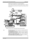
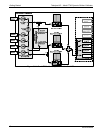
In addition to the connections discussed in the previous sections, this option also
requires the following:
Loop back lines must be connected between:
PHOTOMETER OUTLET fixture and the PHOTOMETER INLET fixture.
PHOTOMETER ZERO OUT fixture and the PHOTOMETER ZERO IN fixture.
An O
3
exhaust line must be connected to the EXHAUST outlet.
06873B DCN6388