


Principles of Operation Teledyne API – Model T700 Dynamic Dilution Calibrator
286
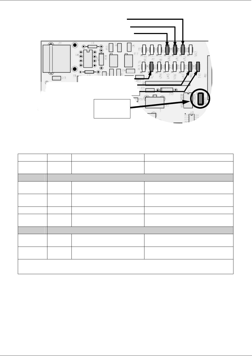
D15 (Yellow) - Photometer Lamp Heater
D16 (Yellow) – O
3
Generator Lamp Heater
D7 (Green) – Photometer Meas/Ref Valve
D8 (Green) O
3
Generator Valve Status
D6 (Green ) – GPT Valve
D9 (Green) – Photometer Pump Status
D1 (RED)
Watchdog
Indicator
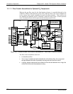
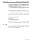
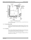
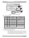
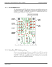
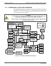
Figure 10-7: Status LED Locations – Relay PCA
Table 10-1: Relay PCA Status LEDs
LED COLOR DESCRIPTION FUNCTION
D1 Red
Watchdog Circuit; I
2
C bus
operation.
Blinks when I
2
C bus is operating properly
D2-6
SPARE
D7
1
Green Photometer Meas/Ref Valve
When lit the valve opens the
REFERENCE gas path
D8
2
Green O
3
generator Valve status
When lit the valve open to O
3
generator
gas path
D9
Green Photometer Pump status When lit the pump is turned on.
D6
1,2
Yellow GPT Valve status
When lit the valve opens the GT
Chamber
D10 - 14 SPARE
D15
1
Yellow Photometer Heater Status
When lit the photometer UV lamp heater
is on
D16
2
Yellow O
3
Generator Heater Status
When lit the O
3
generator UV lamp heater
is on
1
Only applies on calibrators with photometer options installed.
2
Only applies on calibrators with O
3
generator options installed.
10.3.3.4. Relay PCA Watchdog Indicator (D1)
The most important of the status LEDs on the relay PCA is the red I
2
C Bus watchdog
LED. It is controlled directly by the calibrator’s CPU over the I
2
C bus. Special circuitry
on the relay PCA watches the status of D1. Should this LED ever stay ON or OFF for
30 seconds (indicating that the CPU or I
2
C bus has stopped functioning) this Watchdog
Circuit automatically shuts all valves and turns off all heaters and lamps.
06873B DCN6388