Teledyne API – Model T700 Dynamic Dilution Calibrator
xiv
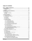
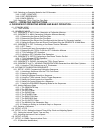
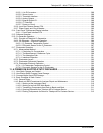
7.3.2. Verifying O3 Photometer Performance............................................................................................... 203
7.3.3. Setup for Calibration of the O3 Photometer ....................................................................................... 204
7.3.3.1. Setup Using Direct Connections ................................................................................................. 204
7.3.3.2. Setup Using a Calibration Manifold............................................................................................. 205
7.3.3.3. Calibration Manifold Exhaust/Vent Line ...................................................................................... 205
7.3.4. Performing an O
3
Photometer External Calibration............................................................................ 205
7.3.4.1. Photometer Zero Calibration ....................................................................................................... 206
7.3.4.2. Photometer Span Calibration ...................................................................................................... 207
7.3.5. O3 Photometer Dark Calibration......................................................................................................... 208
7.3.6. O3 Photometer Gas Flow Calibration................................................................................................. 209
7.3.7. O3 Photometer BackPressure Compensation Calibration ................................................................. 210
7.4. Calibrating the O
3
Generator .................................................................................................................... 211
7.4.1. Setup for Verification and Calibration the O
3
Generator..................................................................... 211
7.4.1.1. Setup Using Direct Connections ................................................................................................. 211
7.4.2. O3 Generator Calibration Procedure.................................................................................................. 213
7.4.2.1. Viewing O
3
Generator Calibration Points .................................................................................... 213
7.4.2.2. Adding or Editing O
3
Generator Calibration Points ..................................................................... 214
7.4.2.3. Deleting O
3
Generator Calibration Points.................................................................................... 215
7.4.2.4. Turning O
3
Generator Calibration Points ON / OFF.................................................................... 216
7.4.2.5. Performing an Automatic Calibration of the Optional O
3
Generator............................................ 217
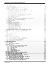
7.5. T700 Gas Pressure Sensor Calibration .................................................................................................... 218
7.5.1.1. Calibrating the Diluent, Cal Gas Optional O
3
Generator Pressure Sensors ............................... 220
7.5.1.2. Calibrating the Optional O
3
Photometer Sample Gas Pressure Sensors ................................... 221
PART III – MAINTENANCE AND SERVICE ........................................................................ 223
8. MAINTENANCE ................................................................................................................ 225
8.1. Maintenance Schedule ............................................................................................................................. 225
8.2. Maintenance Procedures.......................................................................................................................... 227
8.2.1. Auto Leak Check................................................................................................................................. 227
8.2.1.1. Equipment Required.................................................................................................................... 227
8.2.1.2. Setup Auto Leak Check............................................................................................................... 227
8.2.1.3. Performing the Auto Leak Check Procedure............................................................................... 230
8.2.1.4. Returning the T700 to Service after Performing an Auto Leak Check........................................ 230
8.2.2. Cleaning or Replacing the Absorption Tube....................................................................................... 231
8.2.3. UV Source Lamp Adjustment ............................................................................................................. 232
8.2.4. UV Source Lamp Replacement .......................................................................................................... 233
8.2.5. Ozone Generator UV Lamp Adjustment or Replacement .................................................................. 234
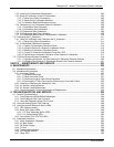
9. TROUBLESHOOTING AND SERVICE............................................................................. 239
9.1. General Troubleshooting .......................................................................................................................... 239
9.1.1. Fault Diagnosis with WARNING Messages........................................................................................ 240
9.1.2. Fault Diagnosis With Test Functions .................................................................................................. 244
9.1.3. Using the Diagnostic Signal I/O Function........................................................................................... 246
9.2. Using the Analog Output Test Channel .................................................................................................... 248
9.3. Using the Internal Electronic Status LEDs................................................................................................ 249
9.3.1. CPU Status Indicator .......................................................................................................................... 249
9.3.2. Relay PCA Status LEDs ..................................................................................................................... 249
9.3.2.1. I
2
C Bus Watchdog Status LEDs.................................................................................................. 249
9.3.2.2. O
3
Option Status LEDs................................................................................................................ 250
9.3.3. Valve Driver PCA STATUS LEDs....................................................................................................... 251
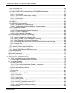
9.4. Subsystem Checkout ................................................................................................................................ 252
9.4.1. Verify Subsystem Calibration.............................................................................................................. 252
9.4.2. AC Main Power................................................................................................................................... 252
9.4.3. DC Power Supply................................................................................................................................ 253
9.4.4. I
2
C Bus................................................................................................................................................ 254
9.4.5. Touchscreen Interface ........................................................................................................................ 254
9.4.6. LCD Display Module........................................................................................................................... 255
9.4.7. Relay PCA .......................................................................................................................................... 255
06873B DCN6388


