


Teledyne API – Model T700 Dynamic Dilution Calibrator Getting Started
37
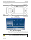
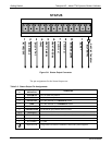
Table 3-2: Rear Panel Description
Component Function
Fan
Cools instrument by pulling ambient air into chassis through side vents and exhausting
through rear.
AC Power
Connector
Connector for three-prong cord to apply AC power to the analyzer
CAUTION! The cord’s power specifications (specs) MUST comply with the
power specs on the calibrator’s rear panel Model number label.
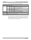
EXHAUST
(option)
Exhaust gas from ozone generator and photometer
CAUTION! Exhaust gas must be vented outside.
PHOTOMETER
INLET
(Photometer option)
Measurement gas input for O
3
photometer
PHOTOMETER
OUTLET
(Photometer option)
Calibration gas outlet to O
3
photometer
PHOTO ZERO IN
(Photometer option)
Inlet for photometer Zero Gas
PHOTO ZERO OUT
(Photometer option)
Outlet for photometer Zero Gas
DILUENT IN
Diluent or zero air gas inlet.
CALGAS OUT
Outlets for calibration gas
VENT
Vent port for output manifold
CYL 1 thru CYL 4
Inlets for up to 4 calibration gases.
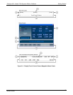
COM 2
Serial communications port for RS-232 or RS-485.
RX TX
LEDs indicate receive (RX) and transmit (TX) activity on the when blinking.
RS-232
Serial communications port for RS-232 only.
DCE DTE
Switch to select either data terminal equipment or data communication equipment
during RS-232 communication. (Section 5.1)
CONTROL OUT
For outputs to devices such as Programmable Logic Controllers (PLCs).
STATUS
For outputs to devices such as Programmable Logic Controllers (PLCs).
ANALOG OUT
For voltage or current loop outputs to a strip chart recorder and/or a data logger.
CONTROL IN
For remotely activating the zero and span calibration modes.
ETHERNET
Connector for network or Internet remote communication, using Ethernet cable.
(optional) USB
Connector for direct connection to a personal computer, using USB cable.
Label w/power specs
Identifies the analyzer model number and lists voltage and frequency specifications
06873B DCN6388