


Troubleshooting and Service Teledyne API – Model T700 Dynamic Dilution Calibrator
250
9.3.2.2. O
3
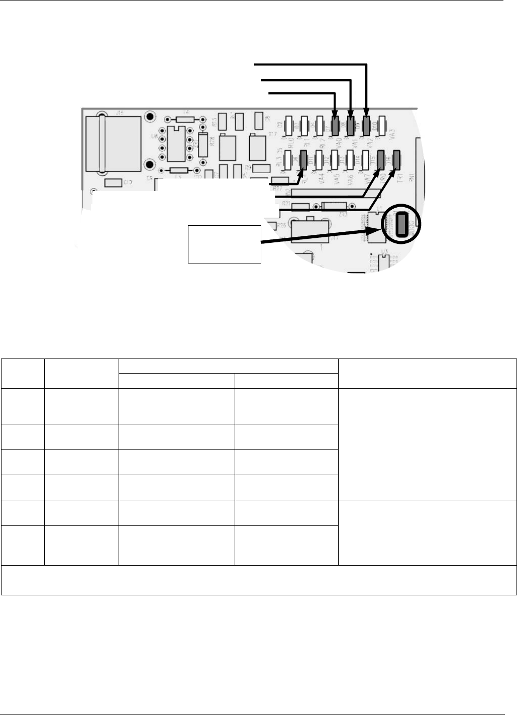
Option Status LEDs
D15 (Yellow) - Photometer Lamp Heater
D16 (Yellow) – O
3
Generator Lamp Heater
D7 (Green) – Photometer Meas/Ref Valve
D8 (Green) O
3
Generator Valve Status
D6 (Green ) – GPT Valve
D9 (Green) – Photometer Pump Status
D1 (RED)
Watchdog
Indicator
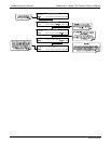
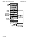
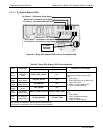
Figure 9-3: Relay PCA Status LEDS Used for Troubleshooting
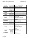
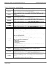
Table 9-5: Relay PCA Status LED Failure Indications
SIGNAL I/O PARAMETER
LED FUNCTION
ACTIVATED BY VIEW RESULT
DIAGNOSTIC TECHNIQUE
D7
1
Green
Photometer
Meas/Ref
Valve
PHOTO_REF_VALVE
N/A
D8
2
Green
O
3
Generator
Valve Status
O3_GEN_VALVE
N/A
D9
1
Green
Photometer
Pump Status
O3-PUMP-ON
N/A
D6
1,2
Yellow
GPT Valve
Status
GPT_VALVE
N/A
Valve should audibly change states.
If not:
Failed Valve
Failed Relay Drive IC on Relay PCA
Failed Relay PCA
Faulty +12 VDC Supply (PS2)
Faulty Connectors/Wiring
D15
1
Yellow
Photometer
Heater Status
PHOTO_LAMP_HEATER PHOTO_LAMP_TEMP
D16
2
Green
O
3
Generator
Heater Status
O3_GEN_HEATER O3_GEN_TEMP
Voltage displayed should change.
If not:
Failed Heater
Faulty Temperature Sensor
Failed AC Relay
Faulty Connectors/Wiring
1
Only applies on calibrators with photometer options installed.
2
Only applies on calibrators with O
3
generator options installed.
06873B DCN6388