


Principles of Operation Teledyne API – Model T700 Dynamic Dilution Calibrator
294
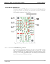
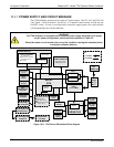
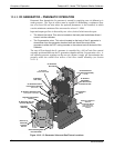
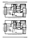
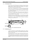
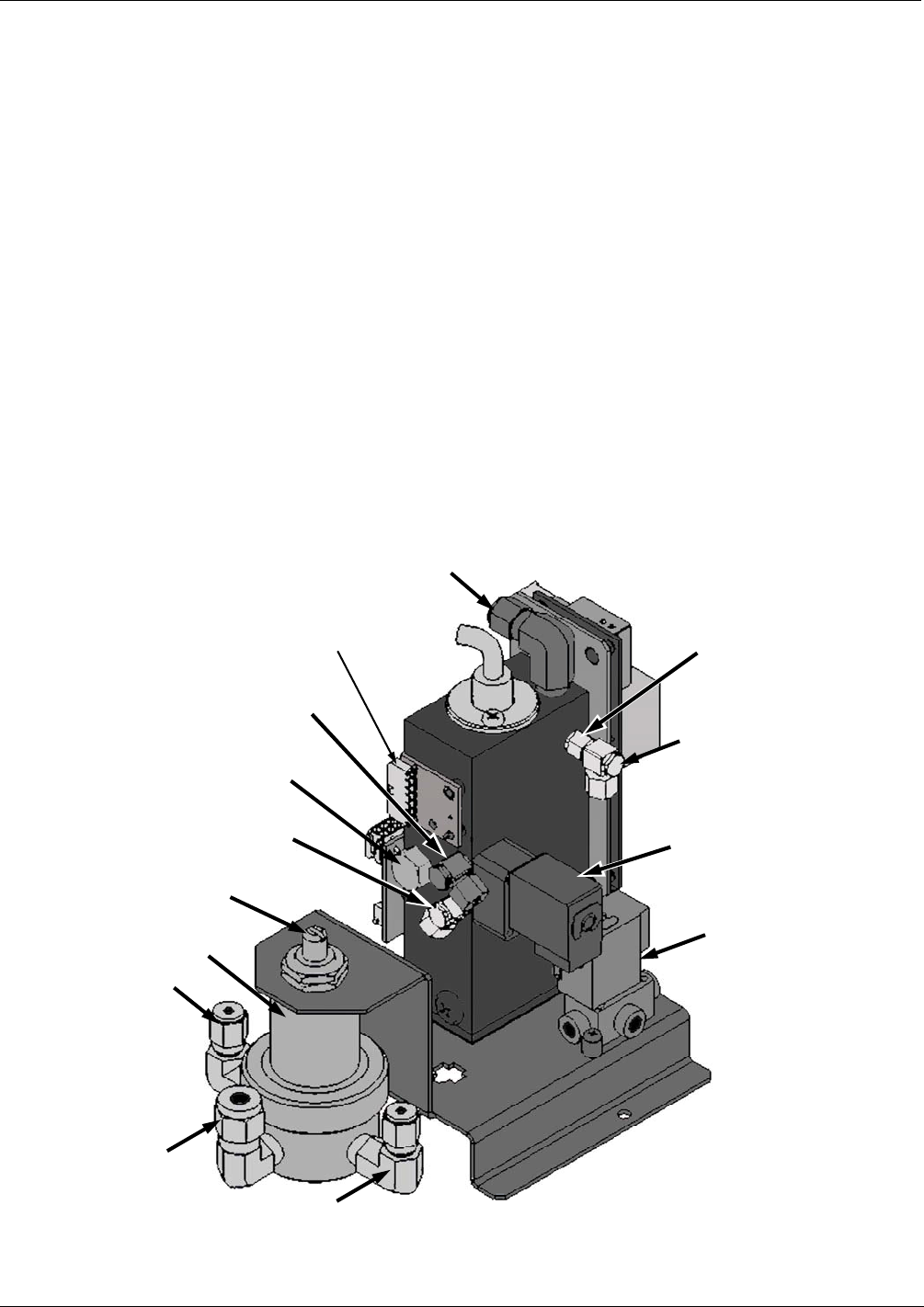
10.6.2. O3 GENERATOR – PNEUMATIC OPERATION
Pneumatic flow through the O
3
generator is created by supplying zero air (diluent) to it
under pressure. The zero air source must be capable of maintaining a continuous flow
rate of at least 100 cm
3
/min unless the optional photometer is also installed, in which
case the minimum continuous flow rate must be at least 1.1 LPM.
Input and output gas flow is directed by two valves, both of which must be open:
The diluent inlet valve: This valve is located on the back panel and allows diluent /
zero air into the calibrator.
The O
3
generation valve: This valve is located on the body of the O
3
generator is
downstream from the generator chamber itself and directs the output of the
generator to either the GPT mixing chamber or the exhaust vent at the back of the
calibrator.
The rate of flow through the O
3
generator is controlled by a 100 cm
3
/min flow control
assembly positioned between the O
3
generation chamber and the O
3
generation valve. A
self adjusting pressure regulator on the zero air (diluent ) supply gas line maintains the
pressure across the critical flow orifice of the flow control assembly (see Section
10.2.1.3).
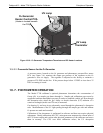
O
3
Generator Zero Air
Pressure Regulator
Regulator Adjustment
Screw
Regulator
Gas Inlet
Outlet to O
3
Generator
Pressure
Sensor
Outlet from Regulator
to O
3
Generator
O
3
Generation
Valve
Measure / Reference
Valve for
Photometer Bench
(only present when
photometer option is
installed)
O
3
Outlet to
Photometer
“Zero Out” fixture
and Internal Vent
Photometer/Vent
Flow Control Assembly
(1.0 LPM)
O
3
Generator
Gas Inlet
O
3
Outlet to
GPT Valve
O
3
Outlet to Exhaust Fixture
(on back panel of calibrator)
O
3
Generator
Heater Control PCA
O
3
Generation Valve
Flow Control Assembly
(100 cm
3
/min)
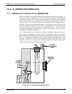
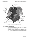
Figure 10-13: O
3
Generator Valve and Gas Fixture Locations
06873B DCN6388