


xi
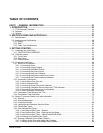
TABLE OF CONTENTS
PART I – GENERAL INFORMATION .................................................................................... 21
1. INTRODUCTION ................................................................................................................. 23
1.1. T700 Calibrator Overview ............................................................................................................................23
1.2. Features.......................................................................................................................................................23
1.3. Options.........................................................................................................................................................24
2. SPECIFICATIONS AND APPROVALS............................................................................... 27
2.1. Specifications...............................................................................................................................................27
2.2. Approvals and Certifications ........................................................................................................................28
2.2.1. Safety.....................................................................................................................................................28
2.2.2. EMC.......................................................................................................................................................29
2.2.3. Other Type Certifications.......................................................................................................................29
3. GETTING STARTED........................................................................................................... 31
3.1. Unpacking and Initial Setup .........................................................................................................................31
3.1.1. VENTILATION CLEARANCE ................................................................................................................32
3.2. Calibrator Layout..........................................................................................................................................32
3.2.1. Front Panel ............................................................................................................................................33
3.2.2. Rear Panel.............................................................................................................................................36
3.2.3. Internal Layout .......................................................................................................................................38
3.3. Connections and Setup................................................................................................................................40
3.3.1. Electrical Connections ...........................................................................................................................40
3.3.1.1. Connecting Power ..........................................................................................................................40
3.3.1.2. Connecting Analog Outputs ...........................................................................................................41
3.3.1.3. Connecting the Status Outputs ......................................................................................................41
3.3.1.4. Connecting the Control Inputs........................................................................................................43
3.3.1.5. Connecting the Control Outputs.....................................................................................................45
3.3.1.6. Connecting the External Valve Driver Option.................................................................................46
3.3.1.7. Connecting the Communications Interfaces ..................................................................................47
3.3.2. Pneumatic Connections.........................................................................................................................54
3.3.2.1. About Diluent Gas (Zero Air)..........................................................................................................54
3.3.2.2. About Calibration Gas ....................................................................................................................54
3.3.2.3. Connecting Diluent Gas to the Calibrator.......................................................................................58
3.3.2.4. Connecting Calibration Source Gas to the T700 Calibrator...........................................................58
3.3.2.5. Connecting Gas Outputs from the Calibrator .................................................................................59
3.3.2.6. Other Pneumatic Connections .......................................................................................................63
3.3.3. Permeation Tube Setup for the T700 ....................................................................................................74
3.3.4. Permeation Tube Calculation ................................................................................................................75
3.4. Startup, Functional Checks, and Initial calibration.......................................................................................77
3.4.1. Start Up..................................................................................................................................................77
3.4.2. Warning Messages ................................................................................................................................77
3.4.3. Functional Checks .................................................................................................................................80
3.4.4. Setting Up the Calibration Gas Inlet Ports.............................................................................................81
3.4.5. Default Gas Types .................................................................................................................................81
3.4.6. User Defined Gas Types .......................................................................................................................81
3.4.6.1. User Defined Gas Types – General ...............................................................................................81
3.4.6.2. User Defined Gas Types – Defining the Gas Name ......................................................................83
3.4.6.3. User Defined Gas Types – Setting the MOLAR MASS..................................................................84
3.4.6.4. Enabling and Disabling Gas Types ................................................................................................86
3.4.7. Defining Calibration Source Gas Cylinders ...........................................................................................87
3.4.7.1. Setting Up the Ports with Single Gas Cylinders.............................................................................87
3.4.7.2. Setting Up the Ports with Multiple Gas Cylinders...........................................................................89
06873B DCN6388