


Troubleshooting and Service Teledyne API – Model T700 Dynamic Dilution Calibrator
240
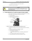
Verify that the DC power supplies are operating properly by checking the
voltage test points on the relay PCA.
Note that the calibrator’s DC power wiring is color-coded and these colors
match the color of the corresponding test points on the relay PCA.
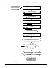
4. Follow the procedures defined in Section 3.4.3 to confirm that the calibrator’s vital
functions are workin
g (power supplies, CPU, relay PCA, etc.).
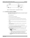
See Figure 3-5 and Figure 3-6 for general layout of components and sub-
assembli
es in
the calibrator.
See the wiring interconnect diagram and interconnect list in Appendix D.
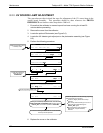
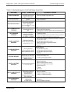
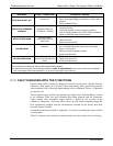
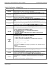
9.1.1. FAULT DIAGNOSIS WITH WARNING MESSAGES
The most common and/or serious instrument failures will result in a warning message
being displayed on the front panel. Table 9-1 lists warning messages, along with their
meaning and recommende
d corrective action.
It should be noted that if more than two or three warning messages occur at the same
time, it is often an indication that some fundamental sub-system (power supply, relay
PCA, motherboard) has failed rather than indication of the specific failures referenced
by the warnings. In this case, it is recommended that proper operation of power supplies
(See Section 9.4.3), the relay PCA (See Section 9.4.7), and the motherboard (See
Section9.4.11) be confirmed before addressing the specific warning messages.
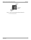
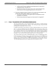
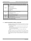
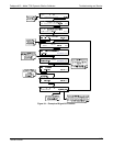
The T700 will alert the user that a War
ning Message is active by flashing the FAULT
LED, displaying the Warning message in the Param field along with the CLR button
(press to clear Warning message). The MSG button displays if there is more than one
warning in queue or if you are in the TEST menu and have not yet cleared the message.
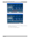
The following display/touchscreen examples provide an illustration of each:
06873B DCN6388