


Teledyne API – Model T700 Dynamic Dilution Calibrator Maintenance
227
8.2. MAINTENANCE PROCEDURES
The following procedures are to be performed periodically as part of the standard
maintenance of the T700 calibrator.
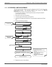
8.2.1. AUTO LEAK CHECK
8.2.1.1. Equipment Required
Four (4) 1/4" Pneumatic caps.
One (1) 1/8” Pneumatic Cap
One (1) # 6 hexagonal Driver/Wrench
One (1) Pneumatic “T” fitting
8.2.1.2. Setup Auto Leak Check
To perform a leak-check on the T700 calibrator:
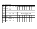
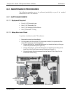
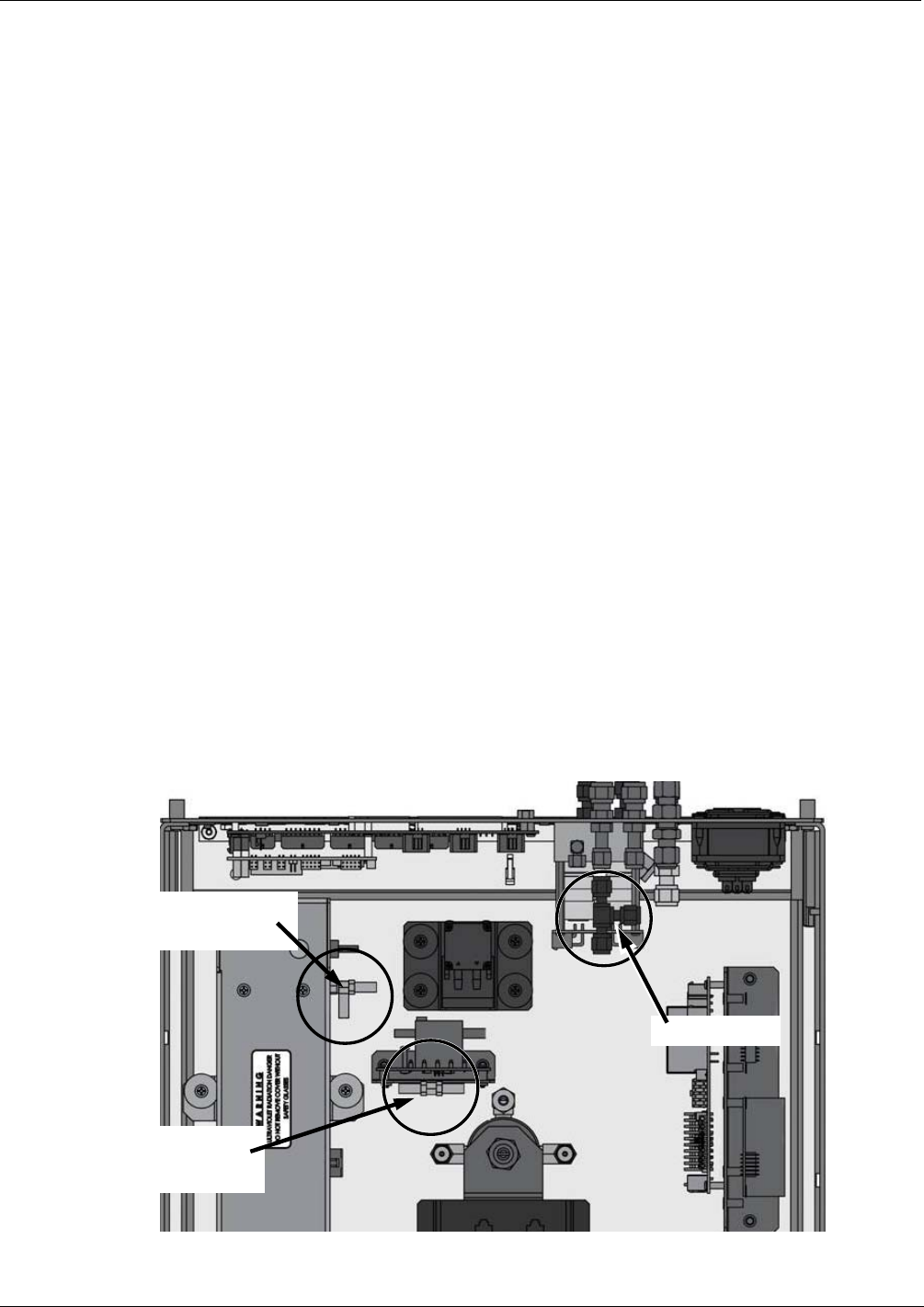
1. Remove the cover from the calibrator.
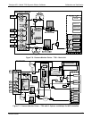
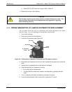
2. On Instruments with the optional O3 photometer installed, the photometer flow
sensor PCA and pump must be bypassed:
Using a #6 nut driver, remove the hexagonal nut located at the top of the gas
outlet of the photometer (see Figure 8-1).
Usi
ng a #6 nut driver, remove the hexagonal nut located on the fitting on the
back side of the Flow/Pressure sensor board (see Figure 8-1).
Con
nect the end of the line removed from the Sensor PCA in Step 3 to the
Photometer Outlet Fitting.
Photometer Gas
Outlet Fitting
Photometer
Flow Sensor / Pump
Outlet Fitting
Internal Vent
Figure 8-1: Bypassing the Photometer Sensor PCA and Pump
06873B DCN6388