


Teledyne API – Model T700 Dynamic Dilution Calibrator Getting Started
45
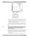
3.3.1.5. Connecting the Control Outputs
The calibrator is equipped with 12 opto-isolated, digital control outputs. These outputs
are activated by the T700’s user-programmable calibration sequences (see Sections
4.3.1.6 and 4.3.2.8 for instructions on assigning the control inputs to specific calibration
sequences).
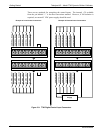
These outputs may
be used to interface with devices that accept logic-level digital
inputs, such as Programmable Logic Controllers (PLCs), data loggers, or digital
relays/valve drivers.
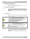
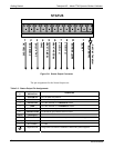
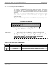
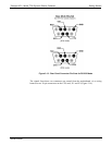
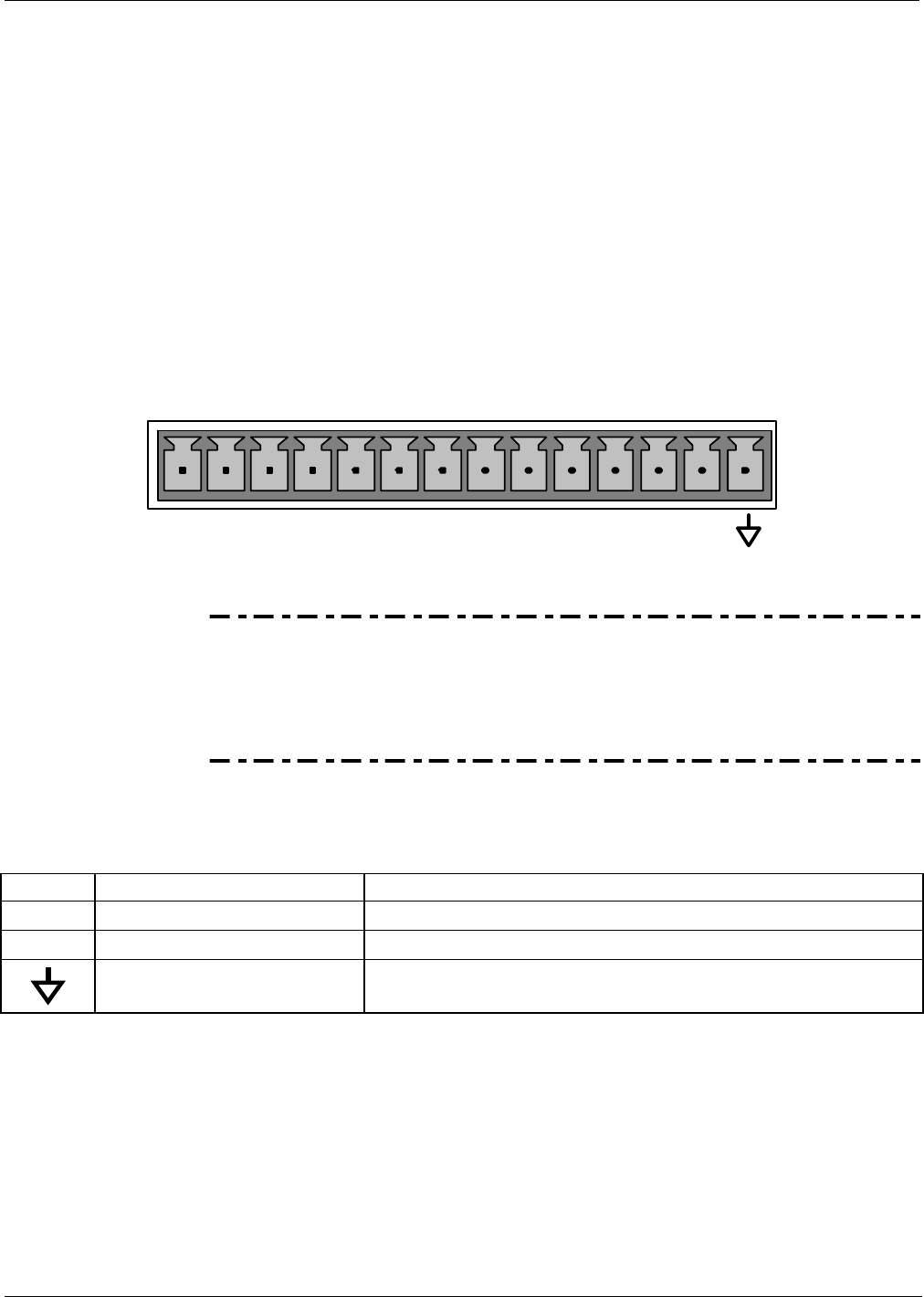
They are accessed via a 14-pin connector on the calibrator’s rear panel (see Figure 3-4).
CONTROL OUTPU
T
S
1 2 3 4 5 6 7 8 9 10 11 12 E
Figure 3-10: T700 Digital Control Output Connector
ATTENTION
COULD DAMAGE INSTRUMENT AND VOID WARRANTY
Most PLCs have internal provisions for limiting the current the input will
draw. When connecting to a unit that does not have this feature, external
resistors must be used to limit the current through the individual
transistor outputs to ≤50mA (120 Ω for 5V supply).
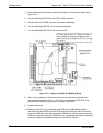
The pin assignments for the control outputs are:
Table 3-5: T700 Control Output Pin Assignments
PIN # STATUS DEFINITION CONDITION
1 - 12 Outputs 1 through 12 respectively Closed if the sequence or sequence step activating output is operating
E Emitter BUS The emitters of the transistors on pins 1 to 12 are bussed together.
Digital Ground The ground level from the calibrator’s internal DC power supplies.
06873B DCN6388