


Teledyne API – Model T700 Dynamic Dilution Calibrator Getting Started
47
057760000A
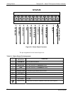
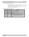
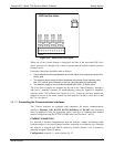
LEADS Val ve Dri ver Interface
+12V IN
Return
ValveDrive 8
ValveDrive 7
Return
ValveDrive 6
ValveDrive 5
Return
ValveDrive 4
ValveDrive 3
Return
ValveDrive 2
ValveDrive 1
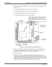
Figure 3-12: Valve Driver PCA Layout
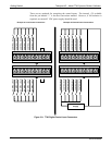
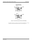
When one of the Control Outputs is energized, the base of the associated PNP valve
driver transistor (U1 through U8) is taken to ground and the emitter-collector junction
becomes active.
Electronic connections should be made as follows:
Valves should be connected between one of the Valve Drive outputs and one of the
Return pins.
The external power supply must be connected to the Valve Driver Interface using
the +12V coaxial input connector on the top, right-hand side of the assembly.
The external supply in turn must be connected to 85-264V, 47-63Hz mains.
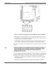
The Valve Driver Outputs are mapped one-for-one to the Control Outputs 1 through 8
and can be manually actuated for troubleshooting using the Signal-I/O diagnostic
function in the T700 software (see Section 9.4.11.5). However, the drive outputs are
mapped in reverse to the status control bits such that Bit-0 (LSB) is valve drive 8 and
Bit-7 is valve drive 1.
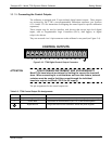
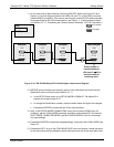
3.3.1.7. Connecting the Communications Interfaces
The T-Series analyzers are equipped with connectors for remote communications
interfaces: Ethernet, USB, RS-232, RS-232 Multidrop and RS-485 (each described
here). In addition to using the appropriate cables, each type of communication method
must be configured using the SETUP>COMM menu (see Sections 4.7 and 5).
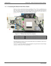
ETHERNET CONNECTION
For network or Internet communication with the analyzer, connect an Ethernet cable
from the analyzer’s rear panel Ethernet interface connector to an Ethernet port. Although
the analyzer is shipped with DHCP enabled by default (Section 5.4), it should be
manually assigned a static IP address.
Configuration
: (manual, i.e., static) Section 5.4.1.1
06873B DCN6388