


Troubleshooting and Service Teledyne API – Model T700 Dynamic Dilution Calibrator
244
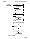
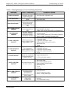
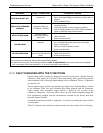
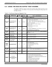
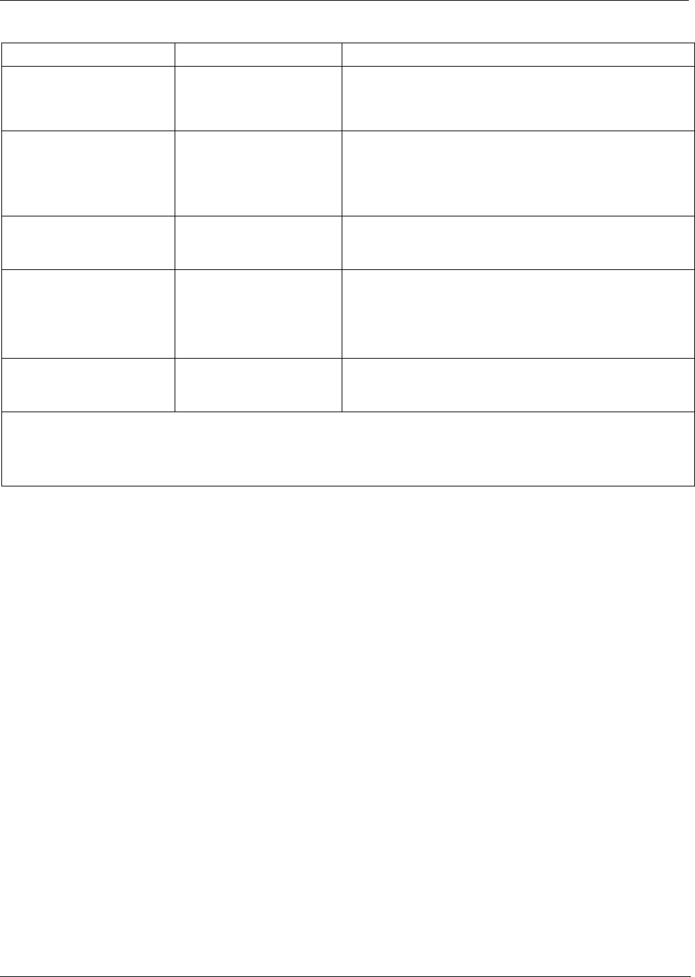
WARNING FAULT CONDITION POSSIBLE CAUSES
REAR BOARD NOT DET
Mother Board not detected
on power up.
- THIS WARNING only appears on Serial I/O COMM
Port(s) Front Panel Display will be frozen, blank or will not
respond.
- Failure of Mother Board
REGULATOR PRESSURE
WARNING
Regulator pressure is
< 15 PSIG or > 25 PSIG.
- Zero or source air supply is incorrectly set up or
improperly vented.
- Incorrectly adjusted O
3
zero air pressure regulator
- Leak or blockage exists in the T700’s internal pneumatics
- Failed O
3
Generator Input pressure sensor
RELAY BOARD WARN
The CPU cannot
communicate with the
Relay PCA.
- I
2
C Bus failure
- Failed relay PCA
- Loose connectors/wiring
SYSTEM RESET
The computer has
rebooted.
- This message occurs at power on.
- If it is confirmed that power has not been interrupted
- Failed +5 VDC power
- Fatal error caused software to restart
- Loose connector/wiring
VALVE BOARD WARN
The CPU is unable to
communicate with the valve
board.
- I
2
C Bus failure
- Failed valve driver PCA
- Loose connectors/wiring
1
Only applicable for calibrators with the optional the O
3
generator installed.
2
Only applicable for calibrators with the optional photometer installed.
3
On instrument with multiple Cal Gas MFCs installed, the MFC FLOW WARNING occurs when the flow rate requested is
<10% of the range of the lowest rated MFC (i.e. all of the cal gas MFC are turned off).
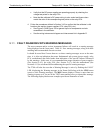
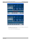
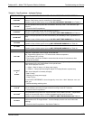
9.1.2. FAULT DIAGNOSIS WITH TEST FUNCTIONS
Besides being useful as predictive diagnostic tools, the test functions viewable from the
calibrator’s front panel can be used to isolate and identify many operational problems
when combined with a thorough understanding of the calibrators Theory of Operation
(see Section 10).
The acceptable ranges
for these test functions are listed in the “Nominal Range” column
of the calibrator Final Test and Validation Data Sheet shipped with the instrument.
Values outside these acceptable ranges indicate a failure of one or more of the
calibrator’s subsystems. Functions whose values are still within acceptable ranges but
have significantly changed from the measurement recorded on the factory data sheet
may also indicate a failure.
A worksheet has been provided in Appendix C to assist in recording the values of these
Test Functions.
Table 9-2 contains some of the more common causes for these values to be out of range.
06873B DCN6388