


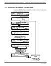

Overview of Operating Modes and Basic Operation Teledyne API – Model T700 Dynamic Dilution Calibrator
148
The ID can also be used for to identify any one of several calibrators attached to the
same network but situated in different physical locations.
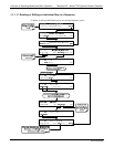
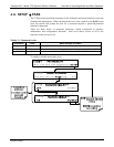
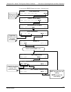
4.7.2. INET (ETHERNET)
Use SETUP>COMM>INET to configure Ethernet communications, whether manually
or via DHCP. Please see Section 5.4 for configuration details.
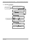
4.7.3. COM1 AND COM2 (MODE, BAUD RATE AND TEST PORT)
Use the SETUP>COMM>COM1[COM2] menus to:
configure communication modes (Section 5.2.1)
view/set the baud rate (Section 5.2.2)
test the con
nections of the com ports (Section 5.2.3).
Configuring COM1 or COM2 requires setting the DCE DTE switch on the rear panel.
Section 5.1 provides DCE DTE information.
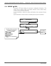
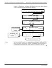
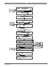
4.8. SETUP MORE FLOW
The Flow menu allows you to view the performance statistics for the Mass Flow
Controllers (MFCs). See Section 7.1 for more information and details on setting up for
MFC flow verification and calibration.
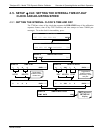
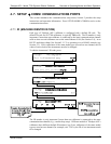
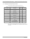
4.9. SETUP MORE VARS: INTERNAL VARIABLES (VARS)
The T700 has several user-adjustable software variables, which define certain
operational parameters. Usually, these variables are automatically set by the
instrument’s firmware, but can be manually redefined using the VARS menu.
The following table lists all variables that are available within the 818 password
protected level. See Appendix A2 for a detailed listing of all of the T700 variables that
are accessible through the remote interface.
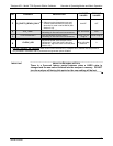
Table 4-12: Variable Names (VARS)
NO. VARIABLE DESCRIPTION
ALLOWED
VALUES
DEFAULT
VALUES
0
PHOTO_LAMP
1,2
Sets the photometer lamp temperature set
point and warning limits.
0ºC and 100ºC
58ºC
Warning limits
56ºC - 61ºC
1
O3_GEN LAMP
1,2
Sets the O
3
generator lamp temperature set
point and warning limits.
0ºC and 100ºC
48ºC
Warning limits
43ºC - 53ºC
2
O3_CONC_RANGE
Set the upper span point of the O
3
concentration range for TEST CHANNEL
analog signal O3_PHOTO_CONC.
0.1–20000 ppb 500 ppb
06873B DCN6388