


Getting Started Teledyne API – Model T700 Dynamic Dilution Calibrator
52
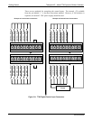
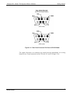
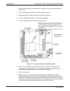
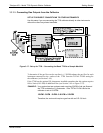
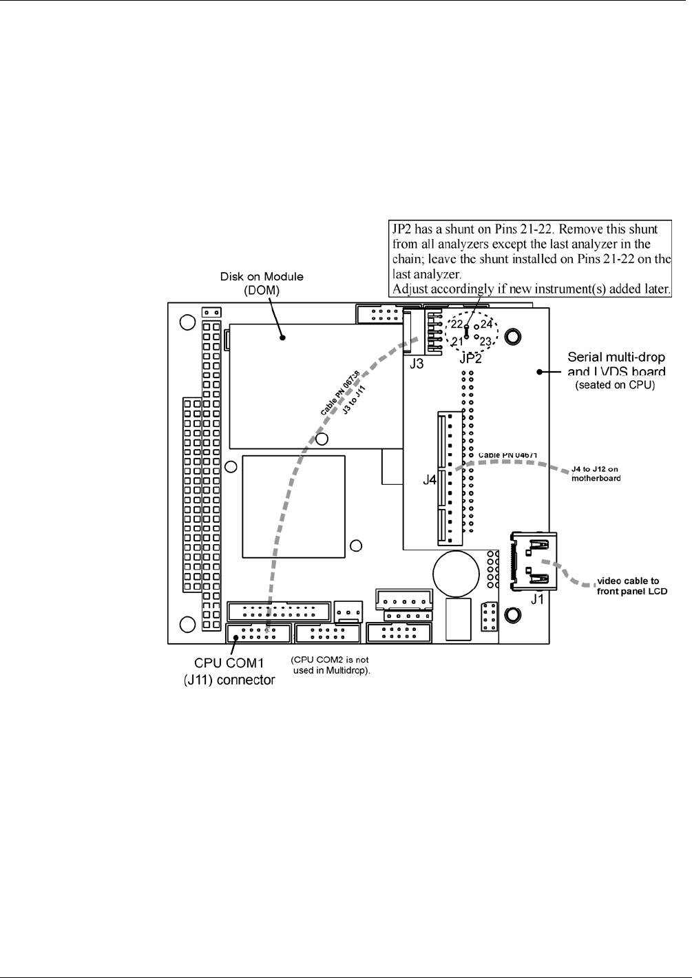
3. Check that the following cable connections are made in all instruments (again refer to
Figure 3-15):
4. J3 on the Mul
tidrop/LVDS PCA to the CPU’s COM1 connector
5. (Note that the CPU’s COM2 connector is not used in Multidrop)
6. J4 on the Multidrop/LVDS PCA to J12 on the motherboard
7. J1 on the Multidrop/LVDS PCS to the front panel LCD
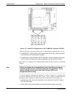
Figure 3-15: Jumper and Cables for Multidrop Mode
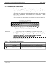
8. (Note: If you are adding an instrument to the end of a previously configured chain,
remove the shunt between Pins 21 22 of JP2 on the Multidrop/LVDS PCA in the
instrument that was previously the last instrument in the chain.)
9. Close the instrument.
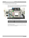
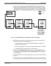
10. Referring to Figure 3-16 use straight-through DB9 male DB9 female c
a
bles to
interconnect the host RS232 port to the first analyzer’s RS232 port; then from the first
analyzer’s COM2 port to the second analyzer’s RS232 port; from the second analyzer’s
COM2 port to the third analyzer’s RS232 port, etc., connecting in this fashion up to eight
analyzers, subject to the distance limitations of the RS-232 standard.
06873B DCN6388