


Principles of Operation Teledyne API – Model T700 Dynamic Dilution Calibrator
304
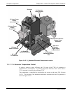
10.7.4.1. O
3
Photometer Temperature Control
In order to operate at peak efficiency the UV lamp of the T700’s O
3
photometer is
maintained at a constant 58ºC. This is intentionally set at a temperature higher than the
ambient temperature of the T700’s operating environment to ensure that local changes in
temperature do not affect the UV Lamp. If the lamp temperature falls below 56ºC or
rises above 61ºC a warning is issued by the calibrators CPU.
This temperature is controlled as described in the section on the relay PCA (Section
10.3.3.2).
The following TEST f
unc
tions report these temperatures and are viewable from the
instrument’s front panel:
PHOTOLTEMP - The temperature of the UV Lamp reported in ºC.
PHOTOSTEMP - The temperature of the Sample gas in the absorption tube
reported in ºC.
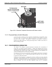
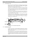
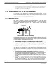
10.7.4.2. Pneumatic Sensors for the O
3
Photometer
The sensors located on the pneumatic sensor just to the left rear of the O
3
generator
assembly measure the absolute pressure and the flow rate of gas inside the photometer’s
absorption tube. This information is used by the CPU to calculate the O
3
concentration
of the sample gas (See Equation 10-7). Both of these measurements are made
downstream from the absorption tube but upstream of the pump. A critical flow orifice
located between the flow sensor and the pump maintains the gas flow through the
photometer at 800 cm
3
/min.
The following TEST functions are viewable from the instrument’s front panel:
PHOTOFLOW - The flow rate of gas through the photometer measured in LPM.
PHOTOSPRESS – the pressure of the gas inside the absorption tube. This
pressure is reported in inches of mercury-absolute (in-Hg-A), i.e. referenced to a
vacuum (zero absolute pressure). This is not the same as PSIG.
06873B DCN6388