


Principles of Operation Teledyne API – Model T700 Dynamic Dilution Calibrator
288
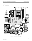
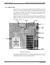
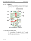
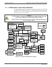
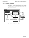
10.3.5. MOTHERBOARD
This is the largest electronic assembly in the calibrator and is mounted to the rear panel
as the base for the CPU board and all I/O connectors. This printed circuit assembly
provides a multitude of functions including A/D conversion, digital input/output, PC-
104 to I
2
C translation, temperature sensor signal processing and is a pass through for the
RS-232 and RS-485 signals.
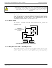
10.3.5.1. A to D Conversion
Analog signals, such as the voltages received from the calibrator’s various sensors, are
converted into digital signals that the CPU can understand and manipulate by the analog
to digital converter (A/D). Under the control of the CPU, this functional block selects a
particular signal input and then coverts the selected voltage into a digital word.
The A/D consists of a voltage-to-frequency (V-F) converter, a programmable logic
device (PLD), three multiplexers, several amplifiers and some other associated devices.
The V-F converter produces a frequency proportional to its input voltage. The PLD
counts the output of the V-F during a specified time period, and sends the result of that
count, in the form of a binary number, to the CPU.
The A/D can be configured for several different input modes and ranges but in uni-polar
mode with a +5V full scale. The converter includes a 1% over and under-range. This
allows signals from -0.05V to +5.05V to be fully converted.
For calibration purposes, two reference voltages are supplied to the A/D converter:
Reference ground and +4.096 VDC. During calibration, the device measures these two
voltages and outputs their digital equivalent to the CPU. The CPU uses these values to
compute the converter’s offset and slope, then uses these factors for subsequent
calculations.
10.3.5.2. Sensor Inputs
The key analog sensor signals are coupled to the A/D converter through the master
multiplexer from two connectors on the motherboard. Terminating resistors (100 kΩ)
on each of the inputs prevent crosstalk between the sensor signals.
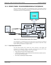
10.3.5.3. Thermistor Interface
This circuit provides excitation, termination and signal selection for several negative-
coefficient, thermistor temperature sensors located inside the calibrator.
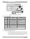
10.3.5.4. Analog Outputs
The T700 calibrator comes equipped with one analog output. It can be set by the user to
output a signal level representing any one of the test parameters (see Table 4-14) and
will output an analog VDC signal that rises and falls in relationship with the value of the
chosen para
meter.
06873B DCN6388