Teledyne API – Model T700 Dynamic Dilution Calibrator
xx
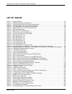
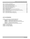
Table 9-2: Test Functions – Indicated Failures .................................................................................................... 245
Table 9-3: Test Channel Outputs as Diagnostic Tools......................................................................................... 248
Table 9-4: Relay PCA Watchdog LED Failure Indications ................................................................................... 249
Table 9-5: Relay PCA Status LED Failure Indications ......................................................................................... 250
Table 9-6: Valve Driver Board Watchdog LED Failure Indications ...................................................................... 251
Table 9-7: Relay PCA Status LED Failure Indications ......................................................................................... 251
Table 9-8: DC Power Test Point and Wiring Color Codes ................................................................................... 253
Table 9-9: DC Power Supply Acceptable Levels.................................................................................................. 254
Table 9-10: Relay PCA Control Devices .............................................................................................................. 255
Table 9-11: Analog Output Test Function – Nominal Values Voltage Outputs.................................................... 259
Table 9-12: Status Outputs Check ....................................................................................................................... 260
Table 9-13: T700 Control Input Pin Assignments and Corresponding Signal I/O Functions............................... 261
Table 9-14: Control Outputs Pin Assignments and Corresponding Signal I/O Functions Check ........................ 262
Table 10-1: Relay PCA Status LEDs.................................................................................................................... 286
Table 10-2: T700 Photometer Measurement / Reference Cycle.......................................................................... 299
Table 11-1: Static Generation Voltages for Typical Activities .............................................................................. 306
Table 11-2: Sensitivity of Electronic Devices to Damage by ESD ....................................................................... 306
LIST OF APPENDICES
APPENDIX A - VERSION SPECIFIC SOFTWARE DOCUMENTATION
APPENDIX A-1: T700 Software Menu Trees, Revision B.7
APPENDIX A-2: T700 Setup Variables Available Via Serial I/O, Revision B.7
APPENDIX A-3: T700 Warnings and Test Measurements via Serial I/O, Revision B.7
APPENDIX A-4: T700 Signal I/O Definitions, Revision B.7
APPENDIX A-5: Model T700 Terminal Command Designators, Revision B.7
APPENDIX B - T700 SPARE PARTS LIST
APPENDIX C - REPAIR QUESTIONNAIRE
APPENDIX D - ELECTRONIC SCHEMATICS
06873B DCN6388


