


Teledyne API – Model T700 Dynamic Dilution Calibrator Troubleshooting and Service
255
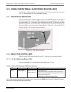
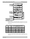
9.4.6. LCD DISPLAY MODULE
Verify the functioning of the front panel display by observing it when power is applied
to the instrument. Assuming that there are no wiring problems and that the DC power
supplies are operating properly, the display screen should light and show the splash
screen and other indications of its state as the CPU goes through its initialization
process.
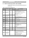
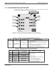
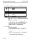
9.4.7. RELAY PCA
The Relay PCA can be most easily checked by observing the condition of the status
LEDs on the Relay PCA (see Section 9.3.2), and using the SIGNAL I/O subm
enu under
the DIAG menu (see Section 4.10) to toggle each LED ON or OFF.
If D1 on
the Relay PCA is flashing and the status indicator for the output in question
(Heater power, Valve Drive, etc.) toggles properly using the Signal I/O function, then
the associated control device on the Relay PCA is bad. Several of the control devices
are in sockets and can be easily replaced. Table 9-10 lists the control device associated
with a particular function.
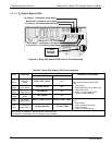
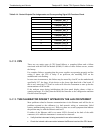
Table 9-10: Relay PCA Control Devices
FUNCTION
CONTROL
DEVICE
IN SOCKET
UV Lamp Heater Q2 No
O
3
Gen Heater Q3 No
All Valves U5 Yes
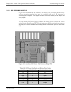
9.4.8. VALVE DRIVER PCA
Like the Relay PCA the valve driver PCA is checked by observing the condition of the
its status LEDs on the Relay Board (see Section 9.3.2), and using the SIGNAL I/O
submenu under the DIA
G menu (see Section 9.1.3) to toggle each LED ON or OFF.
If D2 on the valve driver board is flashing and the status indicator for the output i
n
question (Gas Cyl 1, Purge Valve, etc.) toggles properly using the Signal I/O function,
then the control IC is bad.
06873B DCN6388