


Teledyne API – Model T700 Dynamic Dilution Calibrator Getting Started
51
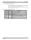
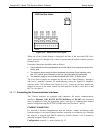
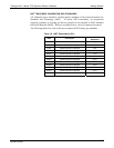
RS-232 COM PORT DEFAULT SETTINGS
Received from the factory, the analyzer is set up to emulate a DCE or modem, with Pin
3 of the DB-9 connector designated for receiving data and Pin 2 designated for sending
data.
RS-232 (COM1): RS-232 (fixed) DB-9 male connector.
Baud rate: 115200 bits per second (baud)
Data Bits: 8 data bits with 1 stop bit
Parity: None
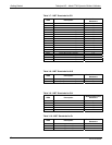
COM2: RS-232 (configurable to RS-485), DB-9 female connector.
Baud rate: 115200 bits per second (baud)
Data Bits: 8 data bits with 1 stop bit
Parity: None
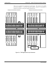
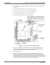
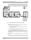
RS-232 MULTI-DROP (OPTION 62) CONNECTION
When the RS-232 Multidrop option is installed, connection adjustments and
configuration through the menu system are required. This section provides instructions
for the internal connection adjustments, then for external connections, and ends with
instructions for menu-driven configuration.
Note Because the RS-232 Multidrop option uses both the RS232 and COM2
DB9 connectors on the analyzer’s rear panel to connect the chain of
instruments, COM2 port is no longer available for separate RS-232 or
RS-485 operation.
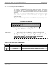
ATTENTION
COULD DAMAGE INSTRUMENT AND VOID WARRANTY
Printed Circuit Assemblies (PCAs) are sensitive to electro-static
discharges too small to be felt by the human nervous system. Failure to
use ESD protection when working with electronic assemblies will void
the instrument warranty. Refer to Section 11 for more information on
preventing ESD damag
e.
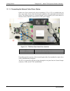
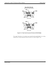
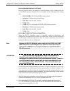
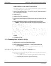
In each instrument with the Multidrop option there is a shunt jumpering two pins on the
serial Multidrop and LVDS printed circuit assembly (PCA), as shown in Figure 3-15.
This shunt must be remo
ved from all instruments except that designated as last in the
multidrop chain, which must remain terminated. This requires powering off and opening
each instrument and making the following adjustments:
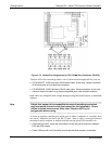
1. With NO power to the instrument, remove its top cover and lay the rear panel open for
access to the Multidrop/LVDS PCA, which is seated on the CPU.
2. On the Multidrop/LVDS PCA’s JP2 connector, remove the shunt that jumpers Pins
21 22 as indicated in. (Do this for all but the last instrument in the chain where the
shunt should remain at Pins 21 22).
06873B DCN6388