


Getting Started Teledyne API – Model T700 Dynamic Dilution Calibrator
42
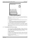
STATUS
1 2 3 4 5 6 7 8 D +
SYSTEM OK
CAL ACTIVE
POWER OK
DIAG
TEMP ALARM
PRESS ALARM
Unassigned
Unassigned
EMITTER BUSS
+ 5 VDC
CALIBRATOR
INTERNAL GROUND
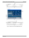
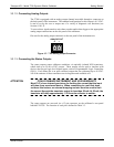
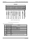
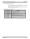
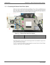
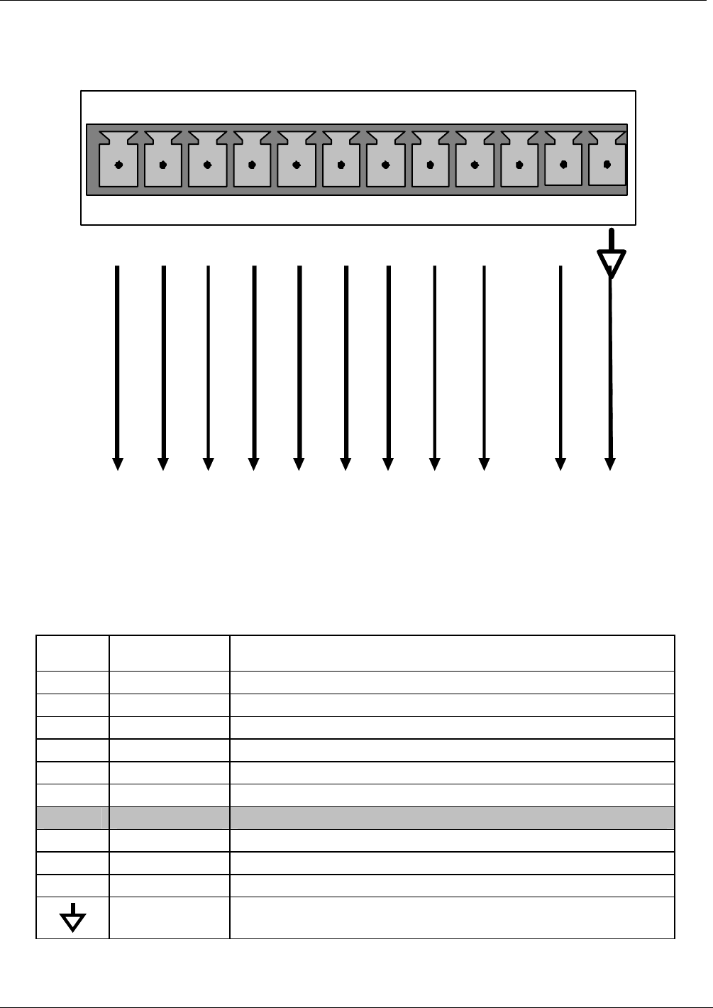
Figure 3-8: Status Output Connector
The pin assignments for the Status Outputs are:
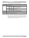
Table 3-3: Status Output Pin Assignments
OUTPUT
#
STATUS
DEFINITION
CONDITION
1
SYSTEM OK
On if no faults are present.
2 POWER OK On if no faults are present.
3
CAL ACTIVE On if the calibrator is in GENERATE mode.
4
DIAG On if the calibrator is in DIAGNOSTIC mode.
5
TEMP ALARM
On whenever a temperature alarm is active.
6
PRESS ALARM
On whenever gas pressure alarm is active.
7 & 8 Unassigned
D Emitter BUS The emitters of the transistors on pins 1 to 8 are bussed together.
(blank) (blank) Not Used
+ DC POWER + 5 VDC
Digital Ground The ground level from the calibrator’s internal DC power supplies.
06873B DCN6388