


Troubleshooting and Service Teledyne API – Model T700 Dynamic Dilution Calibrator
258
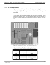
9.4.11. MOTHERBOARD
9.4.11.1. A/D Functions
The simplest method to check the operation of the A-to-D converter on the motherboard
is to use the Signal I/O function under the DIAG menu to check the two A/D reference
voltages and input signals that can be easily measured with a voltmeter.
1. Use the Signal I/O function (See Section 9.1.3 and Appendix A) to view the value of
REF_4096_MV and REF_GND. If both are within 3 mV of nominal (4096 and 0),
and are stable, ±0.5 mV then the basic A/D is functioning properly. If not then the
motherboard is bad.
2. Choose a parameter in the Signal I/O function such as Dil_PRess, MFC_FLOW_1
or SAMPLE_FLOW.
Compare these voltages at their origin (see the interconnect drawing and
interconnect list in Appendix D) with the voltage displayed through the signal I/O
function.
If the wiring is intact but there is a large difference between the measured and
displayed voltage (±10 mV) then the motherboard is bad.
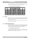
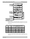
9.4.11.2. Test Channel / Analog Outputs Voltage
To verify that the analog output is working properly, connect a voltmeter to the output in
question and perform an analog output step test as follows:
06873B DCN6388