


Teledyne API – Model T700 Dynamic Dilution Calibrator Maintenance
229
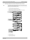
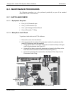
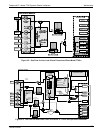
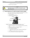
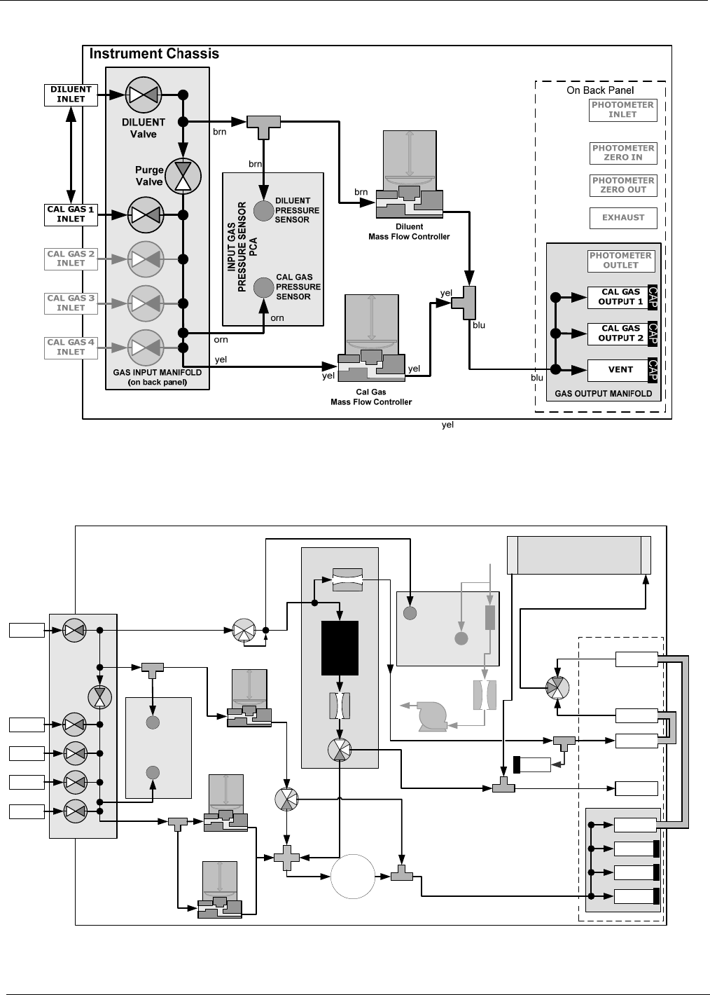
Figure 8-3: Gas Flow for Auto-Leak Check Procedure of Base Model T700’s
Instrument Chassis
DILUENT
PRESSURE
SENSOR
INPUT GAS
PRESSURE SENSOR
PCA
CAL GAS
PRESSURE
SENSOR
PHOTOMETER
PRESSURE SENSOR
O
3
GEN / PHOTOMETER
PRESSURE / FLOW SENSOR PCA
O
3
GAS INPUT
PRESSURE
SENSOR
O
3
FLOW
SENSOR
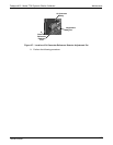
O3 Generator Assembly
O
3
GENERATOR
Flow Control
(1.0 LPM)
Flow Control
(10 cm
3
)
On Back Panel
GAS OUTPUT MANIFOLD
PHOTOMETER
OUTLET
CAL GAS
OUTPUT 2
VENT
CAL GAS
OUTPUT 1
DILUENT
INLET
GAS INPUT MANIFOLD
(on back panel)
Purge
Valve
CAL GAS 1
INLET
CAL GAS 3
INLET
CAL GAS 4
INLET
CAL GAS 2
INLET
Cal Gas
Mass Flow Controller 1
Diluent
Mass Flow Controller
GPT
Volume
PHOTOMETER
INLET
EXHAUST
PHOTOMETER
ZERO OUT
PHOTOMETER
ZERO IN
PHOTOMETER BENCH
OFF
/
Flow Control
(800 cm
3
)
Cal Gas
Mass Flow Controller 2
INTERNAL
VENT
Pressure
Regulator
GPT
Valve
O
3
Gen
Valve
REF/MEAS
Valve
DILUENT
Valve
grn
brn
blk
red
blu
blu
blk
red
vio
vio
wht
CAP
CAP CAP CAP
brn
brn
gry
gry
wht
orn
yel
orn
yel
yel
yel
yel
yel
grn
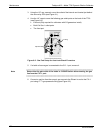
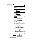
Figure 8-4: Gas Flow for Auto-Leak Check Procedure of T700’s with Optional Photometer
06873B DCN6388