


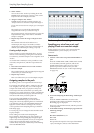
Sampling (Open Sampling System)
124
channel and REC bus 2 is input to the R channel. If you
choose REC3/4, REC bus 3 is input to the L channel
and REC bus 4 is input to the R channel.
Audio Input 1/2, Audio Input 3/4, S/P DIF L/R:
Choose these settings if you want to directly sample
the input from AUDIO INPUT 1–4 or S/P DIF jacks.
The input will be sampled directly without being
routed through the L/R bus, REC buses, or Individual
buses. AUDIO INPUT 1/2 or 3/4 and S/P DIF L/R
will be connected directly, regardless of the “Audio
Input” settings for “Bus Select (IFX/Indiv),” “Bus
(IFX/Indiv),” Pan, and “Level.”
If you choose Audio Input 1/2, AUDIO INPUT 1 is
input to the L channel and AUDIO INPUT 2 is input to
the R channel. If you choose Audio Input 3/4, AUDIO
INPUT 3 is input to the L channel and AUDIO INPUT
4 is input to the R channel.
Indiv.1/2, Indiv.3/4, Indiv.5/6, Indiv.7/8: The Indiv.1/2–
Indiv.7/8 buses will be sampled. Choose these settings
if you want to sample only the audio inputs while
monitoring the L/R outputs, similarly to when using
the REC buses.
If you choose Indiv.1/2, Indiv. bus 1 is input to the L
channel and Indiv. bus 2 is input to the R channel.
Similarly for Indiv.3/4, 5/6, or 7/8, the buses are input
to the L and R channels respectively.
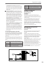
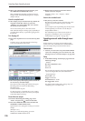
Source Direct Solo
If this is unchecked, the L/R (post-TFX) signal and the
signal of the bus line specified for Source Bus will be
output from the L/R jacks and the headphone jack
according to the Audio Input Bus Select (IFX/Indiv.)
setting and the post-IFX Bus Sel. setting.
Normally you will leave this unchecked, so that
Source Bus and “L/R” are both heard. Check this if
you want to monitor only the sound that’s being
recorded. Only the signal of the bus line selected for
Source Bus will be output from the L/R jacks and the
headphone jack.
Note: If Source Bus is L/R, this setting is ignored, and
the L/R (post-TFX) signal will always be output from
the L/R jacks and headphone jacks.
Trigger
Specifies how sampling will be initiated.
The triggers you can select will differ depending on the
mode.
Sampling mode:
Sampling START SW, Note On, Threshold
Program, Combination mode:
Sampling START SW, Note On
Sequencer mode:
Sampling START SW, Note On, Threshold, Sequencer
START SW
Here we will explain the Sampling START SW and
Note On trigger methods which are available in all
modes. For the trigger mode that’s most appropriate in
various situations, refer to the various examples of
sampling.
Sampling START SW: When you press the
SAMPLING REC, you will enter sampling-standby
mode; sampling will begin when you press the
SAMPLING START/STOP switch.
Note On: Press the SAMPLING REC switch and then
press the SAMPLING START/STOP switch to enter
sampling-standby mode. Sampling will begin when
you play the keyboard.
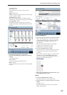
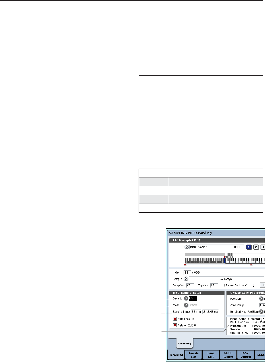
Making settings for the sample to be
recorded
(REC Sample Setup/Sampling Setup)
Next we will specify the location into which the data
will be sampled, select mono or stereo sampling, and
specify the sampling time.
In Sampling mode, these settings are made in REC
Sample Setup. In Combination, Program, and
Sequencer modes, these settings are made in Sampling
Setup. These settings apply only in each respective
mode.
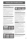
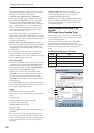
The Recording Setup page in each mode
Sampling mode
Mode Page
Sampling Sampling P0– Recording
Combination Combination P0– Audio Input/Sampling
Program Program P0– Audio Input/Sampling
Sequencer Sequencer P0– Audio Input/Sampling
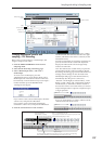
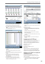
Save to
Mode
Sample Time
Free Sample
Memory /
Free Number