Using Effects
190
For more details, see step 11 under “Program Effects
settings,” beginning on page 185.
Master effects and Total effects
These settings can be made in the same way as in
“Program Effects settings” (p.186).
For details on applying an effect to an external audio
input and sampling the result, refer to p.107.
Sending the output of a multisample to an
effect bus
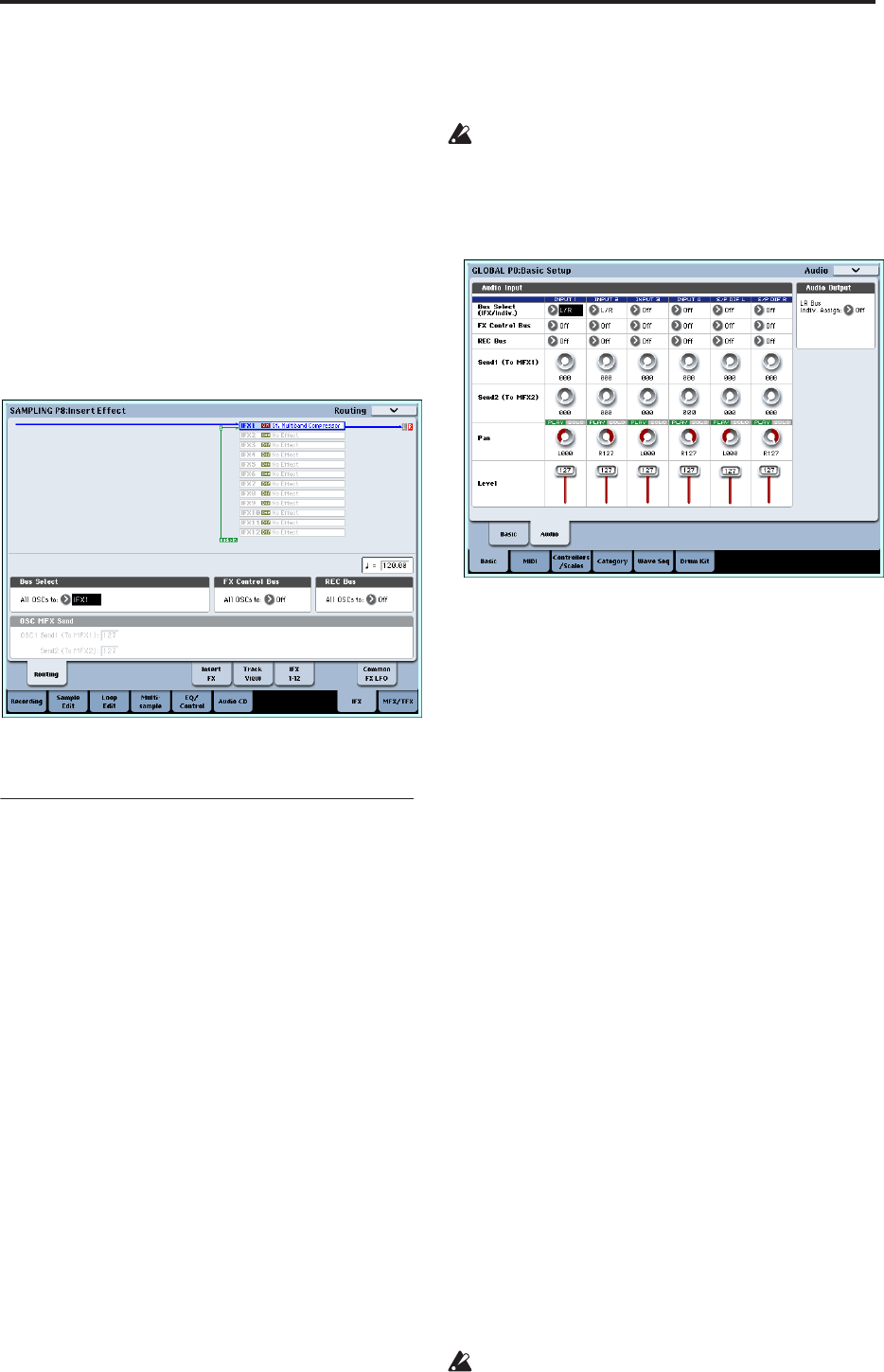
1. If you want the samples assigned to a multisample
to be sent to an effect bus, go to the Sampling P8:
Insert Effect– Routing page, and make settings for
“Bus Select (All OSCs to)”.
For details on applying an effect to a multisample
and resampling, refer to p.108.
Effect settings for the audio inputs
Just as you can in Sampling mode, the Program,
Combination, and Sequencer modes also let you apply
the OASYS’ effects to the signals from the AUDIO
INPUT 1–4 and S/P DIF IN jacks and sample the
result, or to use the OASYS as a 6-in (AUDIO INPUT 1,
2, 3, 4, S/P DIF L, R) 10-out effect processor. You can
also use the OASYS as a vocoder effect (026:Vocoder)
that uses an external mic input to control the internal
sounds.
Input-related settings are made in the P0– Audio
Input/Sampling page of each mode. Normally, you
will make settings in the Global mode P0: Basic Setup–
Audio page and share these settings in all modes, but
you can also make individual settings for a specific
program (in Program mode) if, for example, you want
to use that program as a vocoder.
Routing
1. Access the Global P0: Basic Setup– Audio page.
Note: You must move to Global mode from the
mode (other than Sampling mode) in which you
want to input the external audio signals. If you
move from Sampling mode to Global mode, the
Audio Input settings of Sampling mode will be
maintained, and you won’t be able to view the
settings of this page.
These settings are not used in Sampling mode.
Audio input settings for Sampling mode are made
in the Sampling P0: Recording– Audio Input page.
When applying effects to the signals from the
AUDIO INPUT 1–4 and S/P DIF IN jacks,
oscillation may occur depending on the effect type
and parameter settings. If so, adjust the input level,
output level, and effect parameters. In particular,
use caution when using high-gain effects.
2. Use Bus Select (IFX/Indiv.) to specify the bus to
which each audio input will be sent.
For example if you want the signal from a device
connected to AUDIO INPUT 1 to be input to insert
effect 1, set the INPUT 1 Bus Select (IFX/Indiv.) to
IFX1.
3. Use Send1 and Send2 to specify the send level of
each timbre to the master effects.
This can be set only if Bus Select (IFX/Indiv.) is set
to L/R or Off.
If Bus Select (IFX/Indiv.) is set to IFX1–12, the send
levels to the master effects are set by Send1 and
Send2 (Insert FX page) following the insert effects.
4. Set PLAY/MUTE and Solo On/Off as desired. You
can use the control surface to make these settings.
5. Use Pan to set the panning of the audio input. If
you’re inputting a stereo audio source, you will
normally set the inputs to L000 and R127
respectively.
6. Use Level to adjust the level of the audio input.
Normally you will leave this at 127.
7. FX Control Bus sends the output of the timbre to
an FX Control bus.
Use this when you want the audio input to an effect
to be controlled by another sound. There are two FX
Control buses, which gives you a great deal of
freedom for controlling effects freely. (See PG p.575
“4. FX Control Bus”)
8. REC Bus sends the audio input to a REC bus.
In the P0– Audio Input/Sampling page, you can
choose a REC bus as the Sampling Setup Source
Bus so that the signal sent to the REC bus can be
sampled or recorded (only in Sequencer mode).
Noise can enter the OASYS via these buses; see
“Avoiding extraneous noise” on page 99.


