Overview - What is KARMA? KARMA function settings
205
a certain degree of standardization to the over 200
internal parameters of the GE. By default, GEs that
have the same RTC Model will be preset with the
same GE realtime parameters.
2. Use “VALUE,” “MIN,” and “MAX” to specify the
value, minimum value, and maximum value of
each GE realtime parameter.
When you select a GE, the default parameter values
that are preset for that GE will be assigned.
The values you assign here are controlled as follows
by the KARMA CONTROLS you specify in the
“ASSIGN” field.
3. Use “ASSIGN” to assign each GE realtime
parameter to the desired controller.
4. Use Polarity to specify the polarity of control.
+: Control the parameter as shown in the table
above.
–: The relationship of MIN and MAX will be
inverted. For example as you move a slider from 000
to 127, the value will be controlled from the MAX
value to the MIN value.
Perf RTP (Perf Real-Time Parameters)
Here’s how KARMA parameters such as KARMA
key zone and KARMA module parameters (i.e.,
KARMA parameters other than GE realtime
parameters) can be assigned to controllers.
If you’ve assigned these parameters to KARMA
CONTROLS, you’ll be able to control them in
realtime while you perform (see “Control Surface
knobs, sliders, & switches” on page 47, and “7–6b:
Perf Real-Time Parameters” on page 112 of the
Parameter Guide).
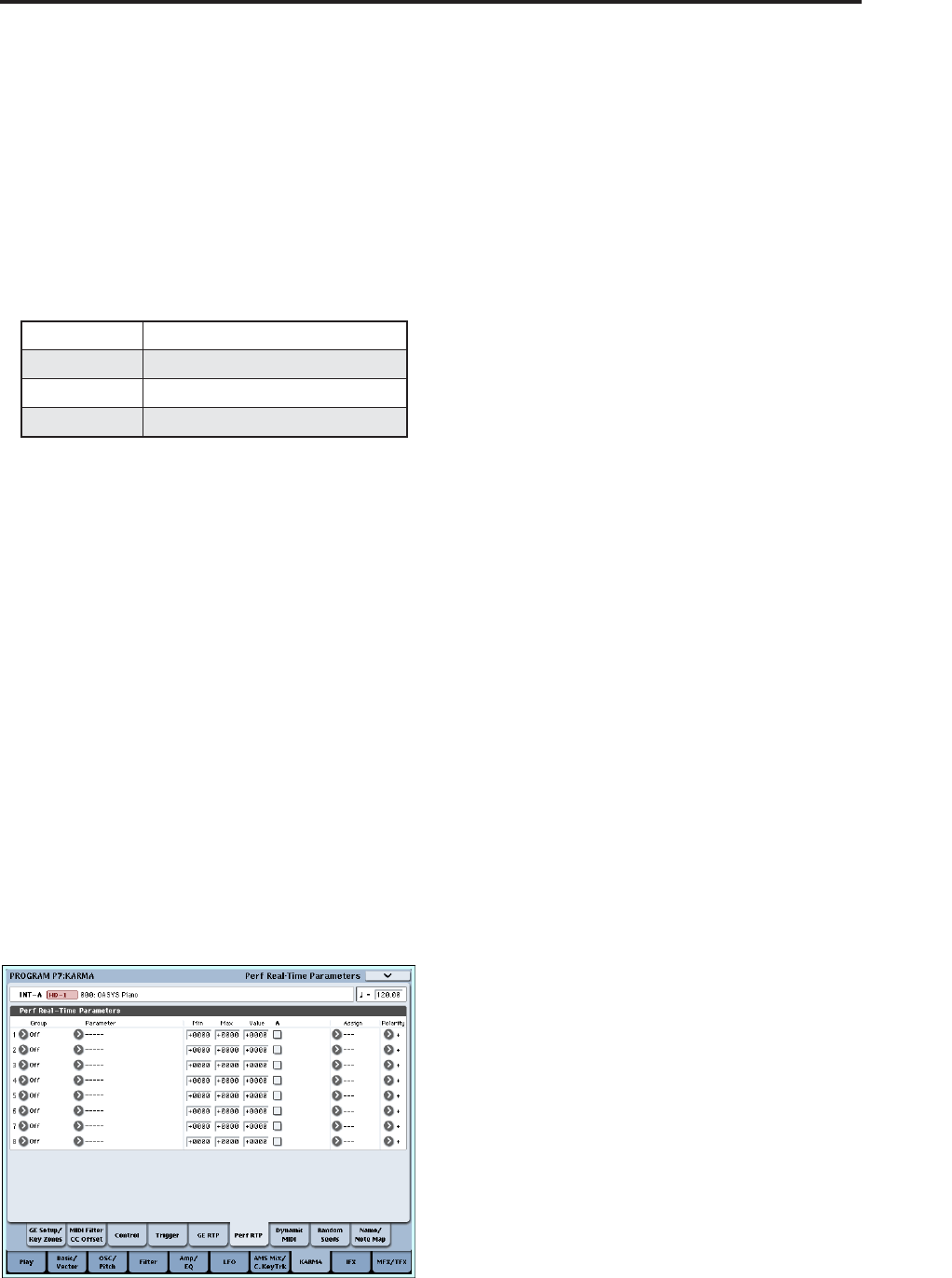
1. Access the Program P7: Perf Real-Time Parameters
page.
As an example, we’ll show how you can use a
KARMA CONTROLS slider to control the KARMA
module parameter “Transpose.”
2. Use “Group” and “Parameter” to select the
parameter you want to control.
For this example, set “Group”: Mix, and
“Parameter”: Transpose. Turn “A” on (checked) so
that the slider will control KARMA module [A].
3. Specify the range and value that you want to
control.
The setting of the parameter will be assigned by
default (–12 in this example), as described under “7–
3b: Module Parameter-Control” on page 103 of the
Parameter Guide.
For this example, set “Min,” “Max,” and “Value” to
–24, +0, and –12 respectively.
4. Use “Assign” to assign the desired controller.
For this example, we’ll assign Slider 1.
5. Use Polarity to specify the polarity of control.
For this example, specify “+”.
When you set CONTROL ASSIGN to R.TIME
KNOBS/KARMA and operate slider 1, the
Transpose setting will change in semitone steps
over a range of –24 to +0, with –12 as the center
value.
Note: If you set “Parameter” to Transpose Octave,
the change will occur in steps of one octave over a
range of –24 to +0, with –12 as the center value.
If you select Transpose Octave/5th, the change will
occur in alternating steps of an octave or a fifth, over
a range of –24 to +0 with –12 as the center value. For
example if this parameter is at the Min setting and a
C3 note is sounding, moving slider 1 from 000
toward 127 will cause a pitch change of C3 → G3 →
C4 → G4 → C5.
Dynamic MIDI setting
Dynamic MIDI lets you use an OASYS controller or a
MIDI control message to control a specific parameter
of the KARMA function. You can specify up to eight
controllers (Source) and what they will do
(Destination). For more information, see “Dynamic
MIDI Sources & Destinations” on page 984 of the
Parameter Guide.
Naming the KARMA RTC sliders 1–8 and switches
1–8
1. Access the Program P7: KARMA– Name/Note
Map page.
Here you can select names for the KARMA
CONTROLS sliders and KARMA SWITCHES. You
can save these settings independently for each
program. The OASYS provides suitable preset
names for the KARMA CONTROLS sliders and
KARMA SWITCHES.
Note:
Auto Assign KARMA RTC Name
An appropriate name for each KARMA
CONTROLS slider and KARMA SWITCH will be
determined based on the GE RTP or Perf RTP being
controlled, and will be assigned automatically. (See
“Auto Assign KARMA RTC Name” on page 139 of
the Parameter Guide.)
Slider 1–8 000-064-127 =MIN-VALUE-MAX
Slider 1–8 (SW) 000-063 = MIN, 064-127 = MAX
SW 1–8 Off = MIN, On = MAX
DynaMIDI 1–8 Depending on Dynamic MIDI setting


