


Playing and editing Programs
60
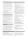
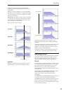
Pitch EG
When the Intensity value is set to +12.00, the pitch EG
specified in the Pitch EG page will produce a
maximum of ±1 octave of pitch change.
To realistically simulate the slight change in pitch that
occurs when a string is plucked or at the attack of a
brass or vocal sound, you can use the EG to create a
subtle change in pitch at the attack.
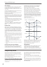
Portamento
Portamento makes the pitch change smoothly when
you play the next note before releasing the previous
note.
The Time parameter controls how long it take the pitch
to change. As this value is increased, the pitch will
change over a longer time. With a value of 000, there
will be no portamento.
You can turn Portamento on and off via SW1 or SW2,
by assigning them to Porta.SW CC#65.
Using Filters
The filters allows you to diminish or emphasize
specified frequency areas of the sound.
The tone of the sound will depend significantly on
the filter settings.
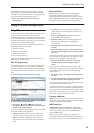
The basic filter settings, including the routing, type,
cutoff frequency, and resonance, are set on the P3:
Filter page.
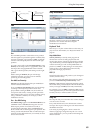
Filter Routing
Each oscillator has two filters, Filter A and Filter B. The
Routing parameter controls whether one or both of the
filters are used, and if both are used, it controls how
they are connected to each other.
The Single routing uses only Filter A as a single 2-pole,
12dB/octave filter (6dB for Band Pass and Band
Reject).
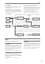
The Serial routing uses both Filter A and Filter B. The
oscillator first goes through Filter A, and then the
output of Filter A is processed through Filter B.
Parallel also uses both Filter A and Filter B. The
oscillator feeds both filters directly, and the outputs of
the two filters are then summed together.
The 24dB/oct. routing merges both filters to create a
single 4-pole, 24dB/octave filter (12dB for Band Pass
and Band Reject). In comparison to Single, this option
produces a sharper roll-off beyond the cutoff
frequency, as well as a slightly more delicate
resonance. Many classic analog synths used this
general type of filter.
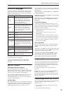
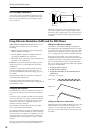
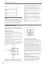
Serial and Parallel Routing
Filter Types
This selects the parts of the sound which will be
affected by the filter, as described below. With the
Serial and Parallel routings, you can independently set
the types for Filter A and Filter B.
The filters will produce very different results
depending on the selected filter type. The selections
will change slightly according to the selected Filter
Routing, to show the correct cutoff slope in dB per
octave.
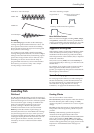
Low Pass. This cuts out the parts of the sound which
are higher than the cutoff frequency. Low Pass is the
most common type of filter, and is used to make bright
timbres sound darker.
High Pass. This cuts out the parts of the sound which
are lower than the cutoff frequency. You can use this to
make timbres sound thinner or more buzzy.
Band Pass. This cuts out all parts of the sound, both
highs and lows, except for the region around the cutoff
frequency. Since this filter cuts out both high and low
Filter A (Low Pass)Oscillator Filter B (High Pass)
Oscillator
Filter A (Low Pass)
Filter B (High Pass)