Using KARMA
208
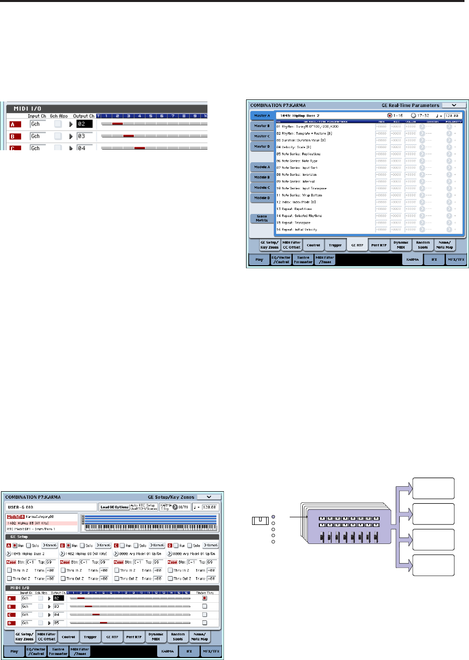
KARMA module B: “Input Ch” = G ch, “Out Ch”=
03
The timbres played by the KARMA modules are
shown in red, as specified by the timbre’s MIDI
channel setting and the KARMA module’s Out
Channel setting.
3. For KARMA modules A and B, turn “Run” on
(checked), and set “GE Select” to GE. (See ““Run”
and “Solo” settings” on page 206.)
KARMA module A: select a bass phrase as the GE
KARMA module B: select a drum phrase as the GE
When the KARMA function is on, your playing on
the keyboard will sound a piano on timbre 1, and
will simultaneously be sent to KARMA modules A
and B.
The bass phrase generated by module A is sent on
MIDI channel 02 to play timbre 2.
The drum phrase generated by module B is sent on
MIDI channel 03 to play timbre 3.
4. Use “Timbre Thru” to specify what will sound
when the KARMA function is off.
When the KARMA function is off, playing the
keyboard will normally sound only the timbres that
match the global MIDI channel (Ch 01).
In this example, this will be the piano sound
produced by timbre 1 (Ch 01).
If “Timbre Thru” is on (checked), you’ll be able to
play timbres that differ from the global channel
when the KARMA function is off.
For KARMA module A, turn “Timbre Thru” on
(checked). When the KARMA function is off,
playing the keyboard will sound the piano of timbre
1 (Ch 01) as well as the bass of timbre 2 (Ch 02).
Editing the parameters of each KARMA
module
You can specify the keyboard zone in which each
KARMA module operates, make MIDI filter settings,
and edit KARMA module parameters. Just as for a
program, these parameters can be specified
independently for each KARMA module.
GE Real-Time Parameters
Here’s how to edit the parameters of the GE selected
for each KARMA module.
1. Access the Combination P7: KARMA– GE Real-
Time Parameters page.
2. In the tabs at the left, select Master A.
3. Set “MIN,” “MAX,” “VALUE,” “ASSIGN,” and
“POLARITY.”
In the Master tabs, specifying “ASSIGN” lets you
edit the “MIN,” “MAX,” “VALUE,” and Polarity
settings.
4. Make settings in the same way for Master B, C,
and D.
The settings you make here are used when
MODULE CONTROL is set to MASTER.
Master lets you control any parameters of modules
A, B, C, or D. You can also use a single controller to
simultaneously control multiple parameters in
different modules; for example, you might use
Slider 1 to control the “Rhythm: Swing%”
parameter of modules A, B, C, and D.
5. In the tabs at the left, select Module A.
6. Set “MIN,” “MAX,” “VALUE,” “ASSIGN,” and
“POLARITY.”
7. Make settings in the same way for Module B, C,
and D.
The “ASSIGN” settings for module A, B, C, and D
are used when MODULE CONTROL is set to A, B,
C, or D respectively.
KARMA REALTIME CONTROLS
KARMA SCENES
KARMA SWITCHES
KARMA CONTROLS
123
4
567
8
MODULE
CONTROL
MASTER
A
B
C
D
KARMA module [D]
KARMA module [C]
KARMA module [B]
KARMA module [A]


