


115
Reference
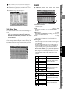
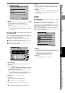
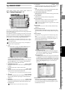
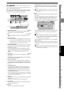
Counter
Rename
METER
CH
VIEW
MIXEREFFECTCDSYSTEMMIDI/
SYNC
TEMPOSONGTRACKUNDO
STORESCENEMARK
SCRUB
LOC1/IN
...LOC6
ENTERMARK
JUMP
REC/PLAY
MODE
Transport
keys
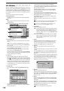
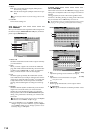
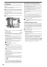
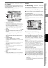
3g. ANALOG COMP
3g-1. Analog Compressor 1–8
Here you can set the analog compressor parameters.
These settings apply compression to the analog inputs of IN-
PUT jacks 1 through 8.
Fifty different compressor settings are stored as preset comp
programs, and there are another fifty user comp programs
that you can rewrite, giving you a total of one hundred pro-
grams that you can recall by using the Recall button.
Comp channels 1–8 correspond to INPUT jacks 1–8; i.e., comp
channel 1 applies to the INPUT 1 jack, and comp channel 2 applies
to the INPUT 2 jack.
Due to the characteristics of analog circuitry, the displayed pa-
rameter values are approximate.
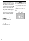
1. Link
Press this button to display the Select Link dialog box.
When compressing a stereo source, you can link adjacent
compression channels and parameters.
Press the channel buttons that you want to link, and then
press the OK button. An “=” symbol will be displayed
between comp channels that are linked.
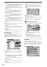
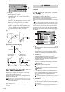
2. THRSHLD (Threshold) [0 dB…–40 dB]
Sets the threshold level at which the compressor begins
to apply.
The displayed value is relative to full scale.
3. RATIO [1.5:1…inf:1]
Sets the compression ratio that will be applied to an input
signal when it exceeds the threshold level.
Setting this to inf (∞):1 will produce the operation of a limiter.
4. ATTACK [1 mS…200 mS]
Sets the speed (attack time) at which the compressor will
begin to apply after the input signal exceeds the thresh-
old level.
5. RELEASE [10 mS…10 S]
Sets the speed (release time) at which the compressor will
stop being applied after the input signal falls below the
threshold level.
Distortion may occur if the release time is too short.
6. OUTGAIN [–20 dB…+20 dB]
Adjusts the output level of the compressor. This lets you
boost a level that was attenuated by compression.
7. ON
Turns the compressor on for the selected channel. When
on, part of the button will be highlighted.
8. Gain reduction (GR) meter
Indicates the reduction in level that is being produced by
the compressor.
9. Comp channel
Indicates the currently selected comp channel.
10.Comp program
Indicates the number and name of the comp program
used by the currently selected comp channel.
This will not be displayed unless a program has been recalled
for the comp channel.
11.Level curve
Displays the level curve of the currently selected comp
channel.
12.IN/OUT/GR bar meters
These bar meters indicate the input/output levels and
gain reduction level for the currently selected comp chan-
nel.
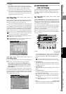
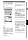
13.Recall button
Changes the comp program for the selected comp chan-
nel.
When you press this button, the Recall dialog box will
appear. Press the Yes button to change the program, or
press the No button to cancel.
13a. Comp channel cell
Selects the comp channel that will use this program.
Press the cell to highlight it, and use the value dial (or
the +/– keys) to select a comp channel.
13b. Program cell
Select the program that you want to use. Press the cell
to highlight it, and use the value dial (or the +/– keys)
to select a comp program. Alternatively, you can press
the popup button located beside the cell to display the
Select Comp Program dialog box, and make your
selection.
14.Store button
Stores the current settings as a compressor program.
Press this button to display the Store Program dialog
box. Press the Yes button to store the program, or press
the No button to cancel.
1
8
11
13
2
3
4
5
6
9
14
7
10
12
13a
13b
MIXER