


5 - 25
MELSEC-Q
5 DATA USED FOR POSITIONING CONTROL
Pr.2
to
Pr.4
Electronic gear
Mechanical system value used when the QD75MH performs positioning control.
The settings are made using
Pr.2
to
Pr.4
.
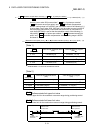
The electronic gear is expressed by the following equation.
No. of pulses per rotation (AP)
Electronic gear =
Movement amount per rotation (AL) Unit magnification (AM)
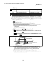
When positioning has been performed, an error (mechanical system error) may
be produced between the specified movement amount and the actual movement
amount. (Refer to Section 12.3.2 "Electronic gear function".)
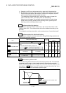
Pr.2
No. of pulses per rotation (AP)
Set the number of pulses required for a complete rotation of the motor shaft.
If you are using the Mitsubishi servo amplifier MR-J3-B set the value given as the
"resolution per servomotor rotation" in the speed/position detector specifications.
No. of pulses per rotation (AP) = Resolution per servomotor rotation
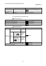
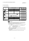
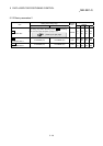
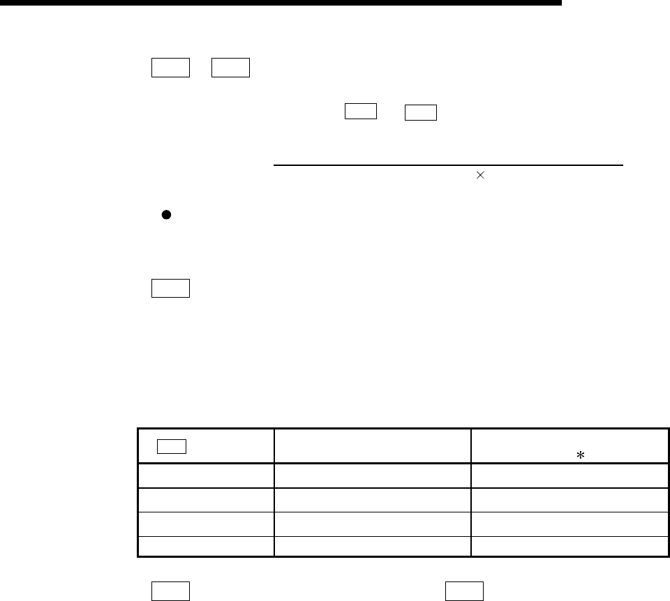
[Table 1]
Pr.1
setting value
Value set with peripheral device
(unit)
Value set with PLC program
(unit)
1
0 : mm
0.1 to 2000000.0 (
µ
m)
1 to 200000000 (
×
10
-1
µ
m)
1 : inch 0.00001 to 2000.00000 (inch)
1 to 200000000 (
×
10
-5
inch)
2 : degree 0.00001 to 2000.00000 (degree)
1 to 200000000 (
×
10
-5
degree)
3 : PLS 1 to 200000000 (PLS) 1 to 200000000 (PLS)
Pr.3
Movement amount per rotation (AL),
Pr.4
Unit magnification (AM)
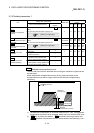
The amount how the workpiece moves with one motor rotation is determined by
the mechanical structure.
If the worm gear lead (
µ
m/rev) is PB and the deceleration rate is 1/n, then
Movement amount per rotation (AL) = PB
×
1/n