


5 - 62
MELSEC-Q
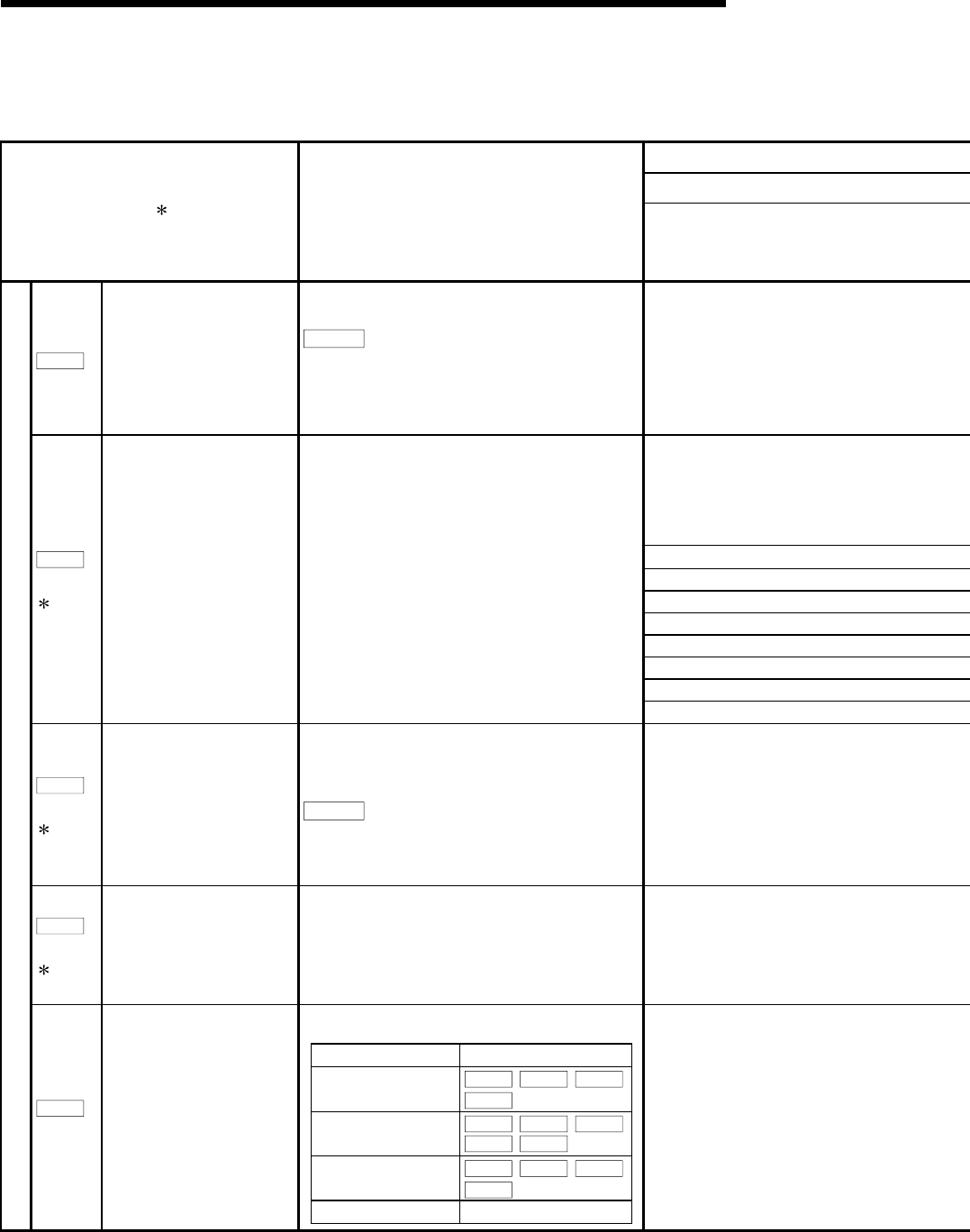
5 DATA USED FOR POSITIONING CONTROL
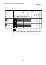
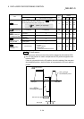
5.2.7 Servo parameters (Basic setting)
Do not set other than the buffer memory addresses of the servo parameters in this section.
Item
2
Setting details
Setting value
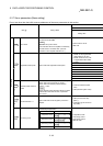
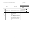
Pr.100
Servo series
Used to select the servo amplifier series, which is
connected to the QD75MH.
POINT
Be sure to set up servo series.
Communication with servo amplifier isn't started by
the initial value "0" in default value. (The LED
indication of servo amplifier indicates "Ab".)
0: Servo series is not set
1: MR-J3-B
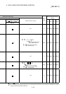
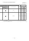
00: Not used
• For MR-J3-10B, regenerative
brake resistor is not used.
• For MR-J3-20B or more, built-
in regenerative brake resistor
is used.
01: FR-BU • FR-RC
02: MR-RB032
03: MR-RB12
04: MR-RB32
05: MR-RB30
06: MR-RB50
08: MR-RB31
Pr.102
(PA02)
3
Regenerative brake option Used to select the regenerative brake option.
09: MR-RB51
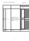
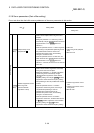
Pr.103
(PA03)
3
Absolute position detection
system
Used to select the absolute position detection system.
When used to the incremental: "0: invalid"
When used to the absolute position detection
system: "1: valid"
POINT
When absolute position detection selection invalid is
selected with incremental encoder, a parameter
error occurs.
0: Invalid (Incremental system
used)
1: Valid (Absolute system used)
Pr.104
(PA04)
3
Function selection A-1
Used to select the forced stop (EM1) of the servo
amplifier.
0: Valid (Use the forced stop
(EM1). )
1: Invalid (Do not use the forced
stop (EM1). )
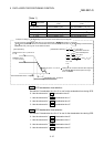
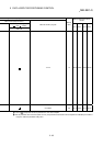
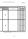
Used to select the gain adjustment.
Automatically set parameters.
Item Parameters
0: Interpolation mode
Pr.124
,
Pr.126
,
Pr.127
,
Pr.128
1: Auto tuning mode 1
Pr.124
,
Pr.125
,
Pr.126
,
Pr.127
,
Pr.128
2: Auto tuning mode 2
Pr.125
,
Pr.126
,
Pr.127
,
Pr.128
3: Manual mode −
Basic setting
Pr.108
(PA08)
Auto tuning mode
0: Interpolation mode
1: Auto tuning mode 1
2: Auto tuning mode 2
3: Manual mode