Appendix - 50
MELSEC-Q
APPENDICES
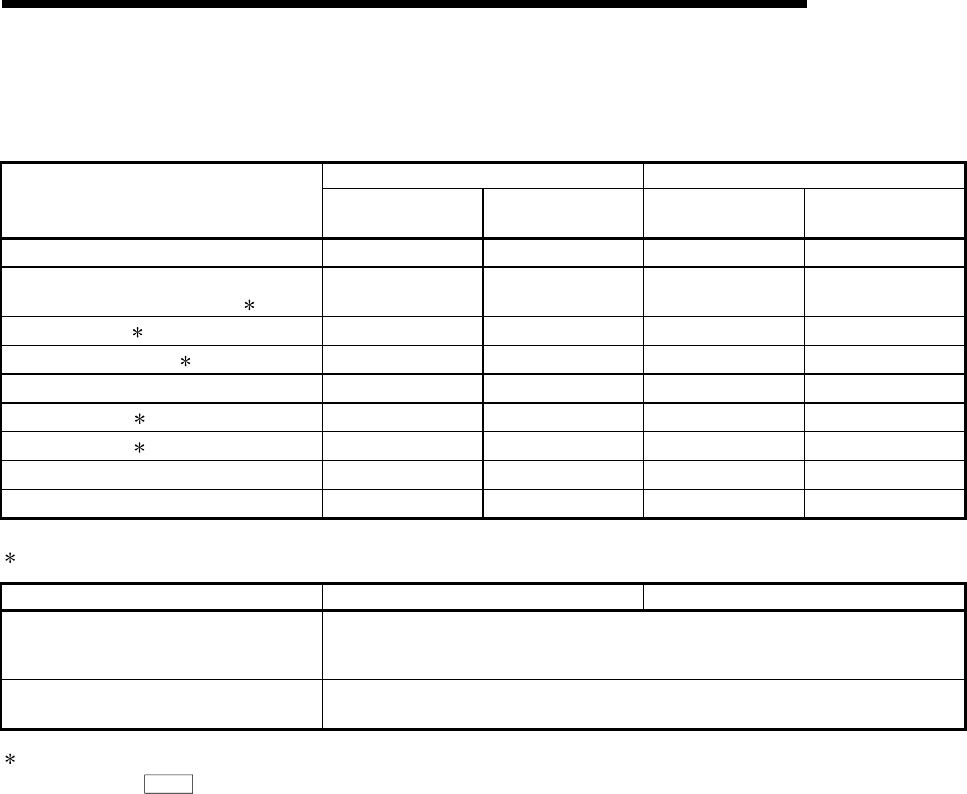
(6) Input/output signal comparisons
Input signal comparisons
QD75M QD75MH
Name
Logic (initial status)
Logic switch with
parameters
Logic (initial status)
Logic switch with
parameters
In-position signal – – – –
Manual pulse generator A phase
Manual pulse generator B phase
1
Negative logic
(multiple of 4)
Possible
Negative logic
(multiple of 4)
Possible
Near-point signal 2 Negative logic Possible Negative logic Possible
Forced stop input signal 2 – – Negative logic Not possible
Stop signal Negative logic Possible Negative logic Possible
Upper limit signal 2 Negative logic Possible Negative logic Possible
Lower limit signal 2 Negative logic Possible Negative logic Possible
External start Negative logic Possible Negative logic Possible
Speed-position switching signal Negative logic Possible Negative logic Possible
1: Comparisons about manual pulse generator A phase/B phase.
QD75M QD75MH
No. of connectable manual pulse
generators
1 generator/1 module
Mode selection (with parameter)
Possible
Multiple of 1 mode, multiple of 2 mode, multiple of 4 mode, PLS/SIGN mode
2: In the case of the QD75MH, the input signal of "Near-point dog signal" and "Upper/lower limit signal" can be used by setting "Detailed
parameters 1" (
Pr.80
External signal selection) .


