


15 - 7
MELSEC-Q
15 TROUBLESHOOTING
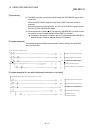
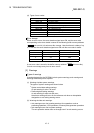
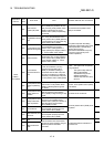
Related buffer memory
address
Axis 1 Axis 2 Axis 3 Axis 4
Set range
(Setting with PLC program)
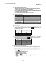
Remedy
— — — — — —
— — — — —
• Check that there is no influence from noise.
• Check hardware for possibility of fault.
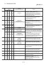
— — — — —
• Review the PLC program which turns ON/OFF PLC
READY signal (Y0).
• Cancel the error with an axis error reset.
(Refer to Section 15.1[3])
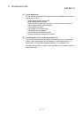
— — — — —
Check the servo amplifier power, wiring with the servo
amplifier, and connection of connectors, and cancel the
error with an axis error reset. (Refer to Section 15.1[3])
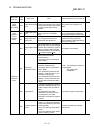
— — — — —
• Check that there is no error on the personal computer
side I/F to which a cable is connected.
• Change the transmission speed (serial communication
baud rate selection) between the personal computer
and the QD75MH. (Refer to Section 5.2.9
Pr.133
)
— — — — —
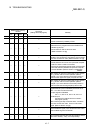
After making an axis error reset (refer to [3] in Section
15.1), perform manual control operation (refer to
Chapter 11) to move the axis to the other position in
order that the upper limit signal (FLS) will turn ON.
— — — — —
After making an axis error reset (refer to [3] in Section
15.1), perform manual control operation (refer to
Chapter 11) to move the axis to the other position in
order that the lower limit signal (RLS) will turn ON.
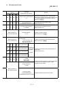
— — — — —
Check whether the stop commands (output
signals/external inputs to QD75MH) are turned ON or
OFF. Turn OFF the ON commands.
• Output signals to QD75MH
Axis 1: Y4, Axis 2: Y5, Axis 3: Y6, Axis 4: Y7
• External input
Connectors for external device connection:
Stop signals (STOP)
After confirming the stop command status, cancel the
error with an axis error reset. Then turn ON a start
signal. (Refer to Section 15.1[3])
— — — — —
The PLC READY signal (Y0) is turned from OFF to ON
when all BUSY signal is turned OFF.
— — — — —
Do not request the start when the axis operation state is
other than "standby", "stop", and "step standby".