


12 - 37
MELSEC-Q
12 CONTROL SUB FUNCTIONS
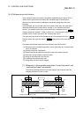
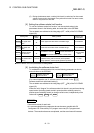
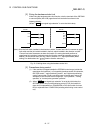
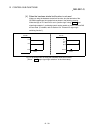
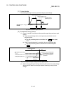
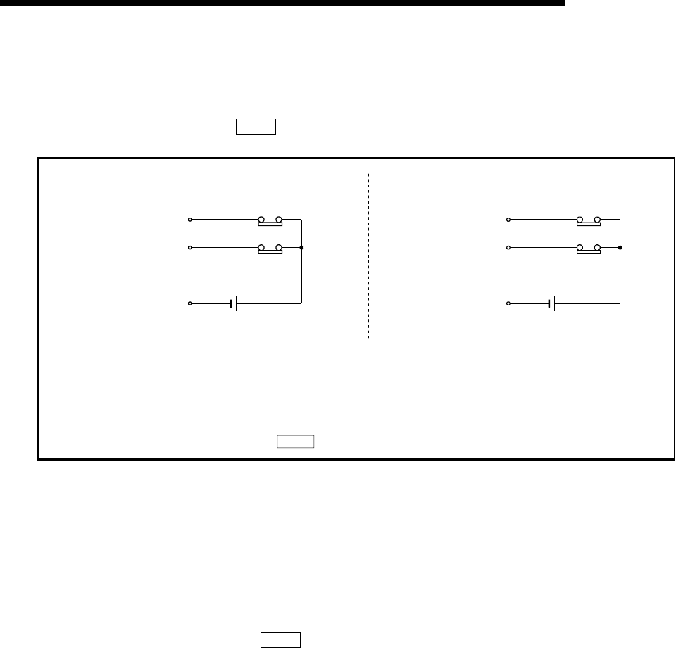
[2] Wiring the hardware stroke limit
When using the hardware stroke limit function, wire the terminals of the QD75MH
or servo amplifier (MR-J3-B) upper/lower limit stroke limit as shown in the
following drawing.
(When "
Pr.22
Input signal logic selection" is set to the initial value)
QD75MH
FLS
RLS
COM
24VDC
MR-J3-B
DI1
(FLS)
DICOM
24VDC
DI2
(RLS)
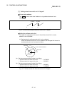
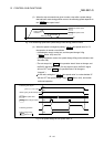
(Note): Wire the limit switch installed in the direction to which "Current feed value" increases as upper
limit switch and the limit switch installed in the limit switch installed in the direction to which
"Current feed value" decreases as lower limit switch. If inverting the install positions of
upper/lower limit switches, hardware stroke limit function cannot be operated properly. In
addition, the servomotor does not stop. Refer to Section 5.2.7 "Servo parameters (Basic
setting)" for details about the "
Pr.114
Rotation direction selection".)
Fig. 12.19 Wiring when using the hardware stroke limit
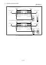
[3] Precautions during control
(1) If the machine is stopped outside the QD75MH control range (outside the
upper/lower limit switches), or if stopped by hardware stroke limit detection,
the "OPR control", "major positioning control", and "high-level positioning
control" cannot start. To carry out these types of control again, return the
workpiece to the QD75MH control range by a "JOG operation", "inching
operation" or "manual pulse generator operation".
(2) When "
Pr.22
Input signal logic selection" is set to the initial value, the
QD75MH cannot carry out the positioning control if FLS (limit switch for
upper limit) is separated from COM/DICOM or RLS (limit switch for lower
limit) is separated from COM/DICOM (including when wiring is not carried
out).