


1 - 24
MELSEC-Q
1 PRODUCT OUTLINE
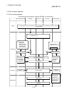
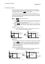
1.2.2 Outline of starting
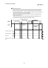
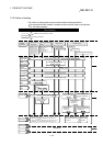
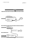
The outline for starting each control is shown with the following flowchart.
It is assumed that each module is installed, and the required system configuration,
etc., has been prepared.
Positioning
data
Block start
data
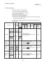
Set the positioning parameters. ( Pr.1 to Pr.42 , Pr.80 to Pr.84 )
Positioning
parameters
( Cd.4 )
( Da.1 to Da.10 )
( Pr.43 to Pr.57 )
Set the OPR parameters.
OPR
parameters
( Da.11 to Da.19 )
( Cd.16 )
Set the servo parameters. ( Pr.100 to Pr.204 )
Servo
parameters
Turn the PLC READY signal ON(Y0 ON)
PLC READY
All axis
servo ON
Turn the All axis servo ON signal(Y1 ON)
Flow of starting
Preparation
Control
functions
Major position-
ing control
High-level positioning
control
OPR control Manual control
Block start (Normal start)
Condition start
Wait start
Simultaneous start
Repeated start
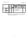
Machine OPR control
Fast OPR control
JOG operation
Inching operation
Manual pulse generator operation
Installation and connection of module
Setting of hardware
Set the positioning data.
Set the positioning start No. ( Cd.3 )
Set the positioning
starting point No.
Set the block start
data.
Input the start signal.
Method (1) Turn ON the QD75MH start signal from the
PLC CPU
Method (2) Issue the PSTRT instruction from the PLC CPU.
Method (3) Turn the QD75MH external start signal ON
Start signal
Control start
Control end
Operation
Stop
Set the inching
movement
amount to 0.
( Cd.16 )
Set the inching
movement
amount to 0.
Set the manual pulse
generator 1 pulse input
magnification.
( Cd.20 )
Set the manual pulse
generator enable flag
to "1".
( Cd.21 )
Set the JOG speed
( Cd.17 )
Control data
Turn the QD75MH JOG
start signal ON from the
PLC CPU
Operate the
manual pulse
generator
Position control
Speed control
Speed-position
switching control
Position-speed
switching control
Other control