


11 - 7
MELSEC-Q
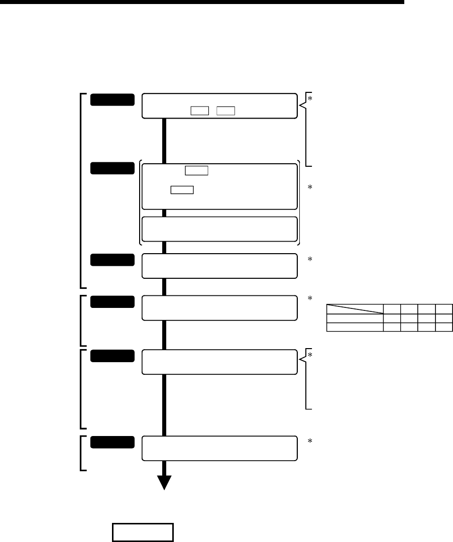
11 MANUAL CONTROL
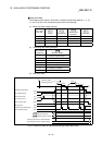
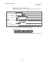
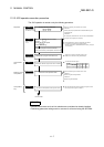
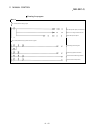
11.2.2 JOG operation execution procedure
The JOG operation is carried out by the following procedure.
STEP 1
Preparation
Refer to Chapter 5
and Section 11.2.3.
End of control
Set the positioning parameters
STEP 2
Refer to Section
11.2.4.
Set the
"
Cd. 17 JOG speed
"
.
STEP 3
Write the PLC program created in STEP 1 and
STEP 2 to the PLC CPU using GX Developer.
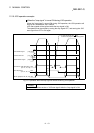
Turn ON the JOG start signal.
STEP 4
One of the following two methods can be used.
<Method 1>
Monitor using GX Configurator-QP.
<Method 2>
Monitor using GX Developer.
One of the following two methods can be used.
<Method 1>
Directly set (write) the parameters in the QD75MH using GX
Configurator-QP.
<Method 2>
Set (write) the parameters from the PLC CPU to the QD75MH
using the PLC program (TO command).
STEP 5
Create a PLC program in which the "JOG start
signal" is turned ON by a JOG operation start command.
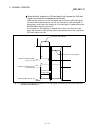
Using GX Developer, set the control data and create a
PLC program for executing the JOG operation.
(Set the control data in the QD75MH buffer memory using the
TO command.)
Write the PLC program to the PLC CPU.
Turn ON the JOG start signal of the axis to be started.
Monitoring of the
J
OG operation
Stop the JOG operation when the JOG start signal is turned
OFF using the PLC program in STEP 2.
STEP 6
Turn OFF the JOG operation start signal that is ON.
Monitor the JOG operation status.
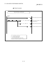
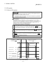
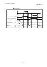
Forward run JOG start signal
Reverse run JOG start signal
Axis 1
Y8
Y9
YA
YB
YC
YD
Refer to Chapter 6.
Axis 3
Axis 2
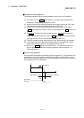
JOG operation
start
JOG operation
stop
to
)
Pr.1
)
Pr.39
(Control data setting)
YE
YF
Axis 4
Set a "0" in " Cd. 16 Inching movement
amount".
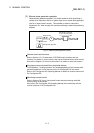
REMARK
•
Mechanical elements such as limit switches are considered as already installed.
•
Positioning parameter settings work in common for all control using the QD75MH.