


5 - 36
MELSEC-Q
5 DATA USED FOR POSITIONING CONTROL
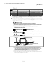
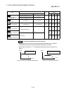
Pr.21
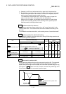
Current feed value during speed control
Specify whether you wish to enable or disable the update of "
Md.20
Current feed
value" while operations are performed under the speed control (including the
speed-position and position-speed switching control).
0: The update of the current feed value is disabled
The current feed value will not change.
(The value at the beginning of the speed control
will be kept.)
1: The update of the current feed value is enabled
The current feed value will be updated.
(The current feed value will change from the
initial.)
2: The current feed value is cleared to zero
The current feed will be set initially to zero and
change from zero while the speed control is in
effect.
Note1: When the speed control is performed over two to four axes, the choice
between enabling and disabling the update of "
Md.20
Current feed value"
depends on how the reference axis is set.
Note2: Set "1" to exercise speed-position switching control (ABS mode).
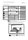
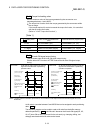
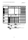
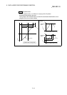
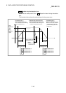
Pr.22
Input signal logic selection
Set the input signal logic that matches the signaling specification of the connected
external device.
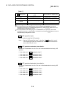
Negative logic
(1) When the input signal contact is not flowed with the current.
(a) FLS, RLS
ON (Limit signal turn ON)
(b) DOG, STOP, CHG
OFF
(2) When the input signal contact is flowed with the current.
(a) FLS, RLS
OFF (Limit signal turn OFF)
(b) DOG, STOP, CHG
ON
Positive logic
Opposite the concept of negative logic.
Note1: A mismatch in the signal logic will disable normal operation. Be careful of
this when you change from the default value.
Note2: Set the manual pulse generator input logic selection (b8) to axis 1. (Setting
of any of axes 2 to 4 is invalid.)
Note3: The lower limit switch logic selection (b0), the upper limit switch logic
selection (b1), and the near-point dog signal logic selection (b3) become
valid when the external input signal of QD75MH/servo amplifier is set to
the "
Pr.80
External signal selection".
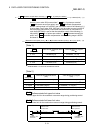
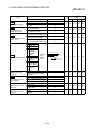
Pr.80
External input signal selection
Set whether to use the external input signal (Upper/lower limit switches, Near-point
dog) for the QD75MH side or servo amplifier side.
0: External input signal of QD75MH
1: External input signal of servo amplifier
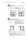
Note1: When external input signal of the servo amplifier is used, the "Count
method 1) or 2)" OPR method can not be used as a near-point dog signal.
("Illegal near-point dog signal error" (error code: 220) occurs when the
positioning starts.)