


15 - 29
MELSEC-Q
15 TROUBLESHOOTING
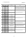
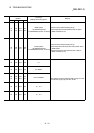
Related buffer memory
address
Axis 1 Axis 2 Axis 3 Axis 4
Set range
(Setting with PLC program)
Remedy
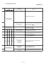
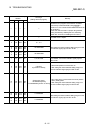
34 184 334 484 0, 2
Speed-position switching control (ABS mode) should
satisfy the conditions 1) to 3) given on the left. When
speed-position switching control (ABS mode) is not
used, set 0 to speed-position function selection and
turn the PLC READY signal [Y0] from OFF to ON.
32 182 332 482 0, 1
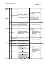
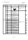
35
0, 1
After setting the value inside the setting range, turn the
PLC READY signal [Y0] from OFF to ON.
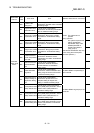
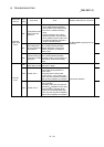
36
37
186
187
336
337
486
487
1 to 8388608
38
39
188
189
338
339
488
489
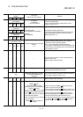
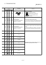
1 to 8388608
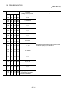
40
41
190
191
340
341
490
491
1 to 8388608
42
43
192
193
342
343
492
493
1 to 8388608
After setting the value inside the setting range, turn the
PLC READY signal [Y0] from OFF to ON.
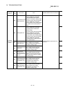
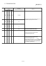
44
45
194
195
344
345
494
495
1 to 8388608
46
47
196
197
346
347
496
497
1 to 8388608
After setting the value inside the setting range, turn the
PLC READY signal [Y0] from OFF to ON.
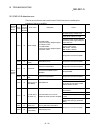
48
49
198
199
348
349
498
499
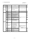
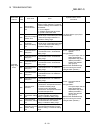
<JOG speed limit value>
1 to 50000000 [PLS/s]
1 to 2000000000 [mm/min or others]
• After setting the value inside the setting range, turn
the PLC READY signal [Y0] from OFF to ON.
• Change the setting into the speed limit value or
below.
50 200 350 500 0, 1, 2, 3
51 201 351 501 0, 1, 2, 3
52 202 352 502 0, 1
After setting the value inside the setting range, turn the
PLC READY signal [Y0] from OFF to ON.