


3 - 21
MELSEC-Q
3 SPECIFICATIONS AND FUNCTIONS
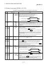
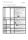
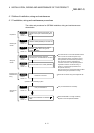
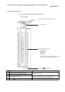
3.4.4 Interface internal circuit
The outline diagrams of the internal circuits for the QD75MH1 external device
connection interface are shown below.
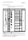
(1) Input
External wiring Pin No. Internal circuit Signal name
Need for wiring
1
1A1
Upper-limit LS signal
4
FLS
1A2
Lower-limit LS signal
4
RLS
1A3
Near-point dog signal
4
DOG
1A4
Stop signal
STOP
1A5
External command
signal/switching signal
CHG
1A6
1B7
Common COM
1A8 EMI
1B8
Forced stop input signal
EMI. COM
(+)
1A19
PULSER A+
(-)
1B19
Manual pulse generator
A phase
PULSER A-
(+)
1A20
PULSER B+
(–)
1B20
Manual pulse generator
B phase
PULSER B–
(5V)
1A15
(5V)
1B15
Manual pulse generator
power supply (+ 5VDC)
3, 5
P5
(0V)
1A14
(0V)
1B14
Manual pulse generator
power supply (GND)
5
SG
When Upper-limit
switch is not used
When Lower-limit
switch is not used
24VDC
5V
0V
A
B
Manual pulse
generator
(MR-HDP01)
2
1A10
5VDC
— — —
1: The symbols in Need for wiring column indicate the following meanings:
•
: Wiring is necessary for positioning. • : Wiring is necessary depending on the situation.
2: Either polarity can be connected to the common (COM).
3: If using separately-placed power supply as manual pulse generator power supply, do not connect power supply 5V(P5) on QD75MH
side. Use separately-placed power supply as 5V stabilized power supply. Using power supply of different voltage between P5 and SG
could lead to faults.
4: When using external input signal of servo amplifier, set "1" with "
Pr.80
External signal selection". In addition, refer to Section 12.4.4
for wiring of upper/lower limit signal and Section 8.1.1 for wiring of near-point dog signal.
5: Do not use P5 and SG for other than manual pulse generator power supply.