


3 - 20
MELSEC-Q
3 SPECIFICATIONS AND FUNCTIONS
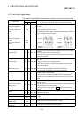
3.4.3 List of input signal details
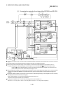
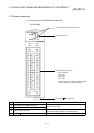
The details of each QD75MH external device connection connector are shown below:
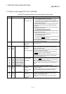
Pin No.
Signal name
AX1 AX2 AX3 AX4
Signal details
(Negative logic is selected by external input signal logic selection)
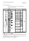
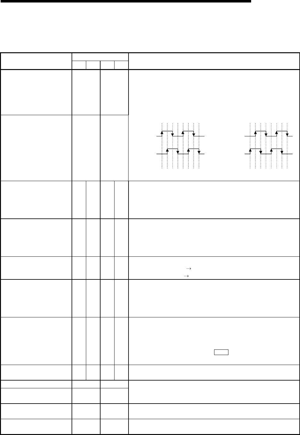
Manual pulse generator A
phase
Manual pulse generator B
phase
1A19
1A20
—
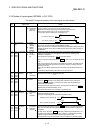
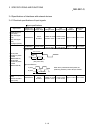
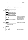
• Input the pulse signal from the manual pulse generator A phase and B
phase.
• If the A phase leads the B phase, the positioning address will increase at the
rising and falling edges of each phase.
• If the B phase leads the A phase, the positioning address will decrease at the
rising and falling edges of each phase.
[When increased] [When decreased]
Manual pulse generator A
common
Manual pulse generator B
common
1B19
1B20
—
+1+1+1+1+1+1+1+1 -1 -1 -1 -1 -1 -1 -1 -1
A phase
B phase
Positioning
address
A phase
B phase
Positioning
address
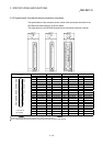
Upper limit signal 1A1 1B1 2A1 2B1
• This signal is input from the limit switch installed at the upper limit position of
the stroke.
• Positioning will stop when this signal turns OFF.
• When OPR retry function is valid, this will be the upper limit for finding the
near-point dog signal.
Lower limit signal 1A2 1B2 2A2 2B2
• This signal is input from the limit switch installed at the lower limit position of
the stroke.
• Positioning will stop when this signal turns OFF.
• When OPR retry function is valid, this will be the lower limit for finding the
near-point dog signal.
Near-point dog signal 1A3 1B3 2A3 2B3
• This signal is used for detecting the near-point dog during OPR.
• The near-point dog OFF ON is detected at the rising edge.
• The near-point dog ON
OFF is detected at the falling edge.
Stop signal 1A4 1B4 2A4 2B4
• Input this signal to stop positioning.
• When this signal turns ON, the QD75MH will stop the positioning being
executed.
After that, even if this signal is turned from ON to OFF, the system will not
start.
External command signal/
switching signal
1A5 1B5 2A5 2B5
• Input a control switching signal during speed-position or position-speed
switching control.
• Use this signal as the input signal of positioning start, speed change request,
and skip request from an external device.
Set the function to use this signal in "
Pr.42
External command function
selection".
Common
1A6
1A7
1B6
1B7
2A6
2A7
2B6
2B7
• Common for upper/lower limit, near-point dog, stop, and external command
signal/switching signals.
Forced stop input signal 1A8 —
Forced stop input signal
common
1B8 —
• This signal is input when batch forced stop is available for all axes of servo
amplifier.
• When this signal turns OFF, the QD75MH will be the forced stop.
Manual pulse generator power
supply (+ 5VDC)
1A15
1B15
— • Power supply for manual pulse generator. (+ 5VDC)
Manual pulse generator power
supply (GND)
1A14
1B14
— • Power supply for manual pulse generator. (GND)