


15 - 25
MELSEC-Q
15 TROUBLESHOOTING
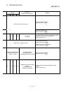
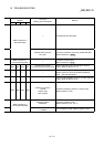
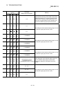
Related buffer memory
address
Axis 1 Axis 2 Axis 3 Axis 4
Set range
(Setting with PLC program)
Remedy
— — — — —
Review the PLC program so that data is not written
continuously to the flash ROM. (Using "
Md.19
" in
Section 5.6.1, the number of flash ROM write times can
be monitored.)
(If this error has occurred in a proper using method,
writing is enabled by resetting the error, switching
power OFF, then ON, or resetting the PLC CPU.)
— — — — — A trouble occurs. Repair.
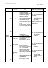
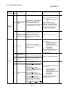
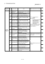
0 150 300 450 0, 1, 2, 3
2
3
152
153
302
303
452
453
1 to 200000000
4
5
154
155
304
305
454
455
1 to 200000000
After setting the value inside the setting range, turn the
PLC READY signal [Y0] from OFF to ON.
1 151 301 451 1,10,100,1000
After setting the "AL x AM" is not less than
2147483647, turn the PLC READY signal [Y0] from
OFF to ON.
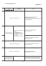
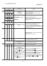
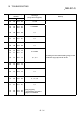
6
7
156
157
306
307
456
457
0 [PLS/s]
0 [mm/min or others]
• Set the bias speed to not more than "0".
• After setting the value inside the setting range, turn
the PLC READY signal [Y0] from OFF to ON.
10
11
160
161
310
311
460
461
<Speed limit value>
1 to 50000000 [PLS/s]
1 to 2000000000 [mm/min or others]
• Set a value which is not less than the home position
return (OPR) speed.
• After setting the value inside the setting range, turn
the PLC READY signal [Y0] from OFF to ON.
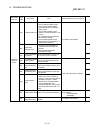
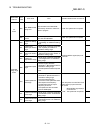
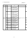
12
13
162
163
312
313
462
463
1 to 8388608
14
15
164
165
314
315
464
465
1 to 8388608
After setting the value inside the setting range, turn the
PLC READY signal [Y0] from OFF to ON.