


3 - 23
MELSEC-Q
3 SPECIFICATIONS AND FUNCTIONS
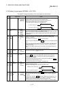
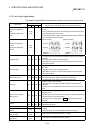
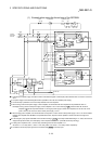
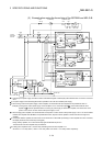
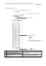
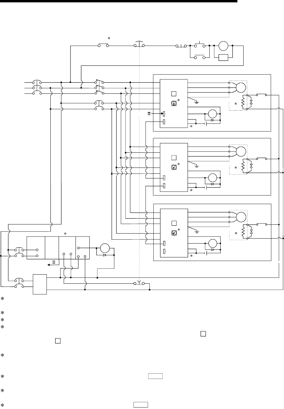
(1) Example when using the forced stop of the QD75MH
CP3
QY41PQD75MHQnCPU
Q61P-A2
CP1
CP2
A
CN1A
CN1B
DICOM
ALM
EM1
DOCOM
0
SM
U
V
W
Servomotor
Ground
Electromagnetic
breake
2
Ra2
Ra2
MR-J3-B
Servo amplifer
U
V
W
L1
L2
L3
L11
L21
SSCNET
EMI.
COM EMI
COM
3-phase
200VAC to
230VAC
NFB
MC
Ra1
Alarm
1
Forced stop Operation ready
OFF ON
MC
MC
SK
Alarm
24VDC
Powerr
supply
24VDC
24GDC
Ra1
Forced stop
SSCNET
24VDC
3
7
8
B
CN1A
CN1B
DICOM
ALM
EM1
DOCOM
1
SM
U
V
W
Servomotor
Ground
Electromagnetic
breake
2
Ra3
Ra3
MR-J3-B
Servo amplifer
U
V
W
L1
L2
L3
L11
L21
24VDC
3
7
C
CN1A
CN1B
DICOM
ALM
EM1
DOCOM
2
SM
U
V
W
Servomotor
Ground
Electromagnetic
breake
2
Ra4
Ra4
MR-J3-B
Servo amplifer
U
V
W
L1
L2
L3
L11
L21
24VDC
3
7
1: Configure up the power supply circuit which switch off the electromagnetic contactor (MC) after detection alarm occurrence on the PLC
CPU.
2: The power supply for the electromagnetic brake is possible to use a full wave rectified power supply.
3: The forced stop is possible to use a forced stop terminal of the servo amplifier.
4: When turning off the control power supply of servo amplifier, communication with servo amplifier is not possible from then on.
Example) If turning off the control power supply of servo amplifier L11/L21 in the above figure
B
, communication with the servo
amplifier of
C
cannot be performed either. For turning off power supply of certain servo amplifier, turn off the main circuit
power L1/L2/L3, but do not turn off the control power supply L11/L21.
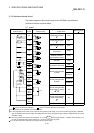
5: When changing servo amplifier, turn off both the main circuit power L1/L2/L3 and the control power supply L11/L21. As communication
between servo amplifier and QD75MH is not possible at this time, stop the machine operation in advance and then change servo
amplifier.
6: If the emergency stop signal of QD75MH turns OFF when setting of
Pr.82
Forced stop valid/invalid setting to "0 : Valid", servomotor is
stopped with dynamic brake. (The LED display of servo amplifier indicates "E7" (Controller forced stop warning).)
7: If setting servo amplifier to Axis 1, set the rotary axis setting switch of servo amplifier to "0".
Set "Axis2 => 1 for rotary switch", "Axis3 => 2 for rotary switch" and "Axis4 => 3 for rotary switch" respectively.
8: The status of forced stop input signal can be confirmed with
Md.50
Forced stop input.