


15 - 3
MELSEC-Q
15 TROUBLESHOOTING
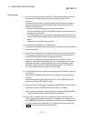
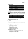
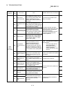
(4) Types of error codes
Error code Classification of errors
001 to 009 Fatal errors
100 to 199 Common errors
200 to 299 OPR or absolute position restoration errors
300 to 399 JOG operation or inching operation errors
500 to 599 Positioning operation errors
800 to 899 I/F (Interface) errors
900 to 999 Parameter setting range errors
1201 to 1209 Encoder errors
2000 to 2099 Servo amplifier errors
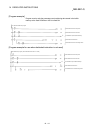
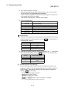
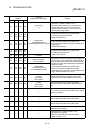
Error storage
When an error occurs, the error detection signal turns ON, and the error code
corresponding to the error details is stored in the following buffer memory address
(
Md.23
Axis error No.) for axis error No. storage. Note that there is a delay of up
to 1.7ms after the error detection signal turns ON until the error code is stored.
Axis No. Error detection signal Buffer memory address
1 X8 806
2 X9 906
3 XA 1006
4 XB 1106
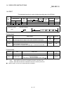
A new error code is stored in the buffer memory address (
Md.23
Axis error No.)
for axis error storage every time an error occurs.
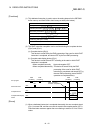
[2] Warnings
Types of warnings
Warnings detected by the QD75MH include system warnings, axis warnings and
warnings detected by servo amplifier.
(1) Warnings include system warnings.
The types of system warnings are shown below.
•
System control data setting warnings
An axis warning for axis 1 will occur.
•
Positioning data setting warnings
An axis warning for each axis will occur.
Note that a warning will occur for the reference axis when an interpolation
designation or axis setting warning occurs.
(2) Warnings include axis warnings.
•
Axis warnings occur due to setting warnings from operations such as
positioning operations, JOG operations or manual pulse generator operations.
•
Axis warnings occur due to system warnings.
The axis operation status does not change even if an axis warning occurs.