


1 - 7
MELSEC-Q
1 PRODUCT OUTLINE
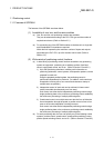
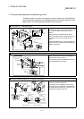
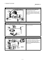
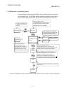
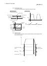
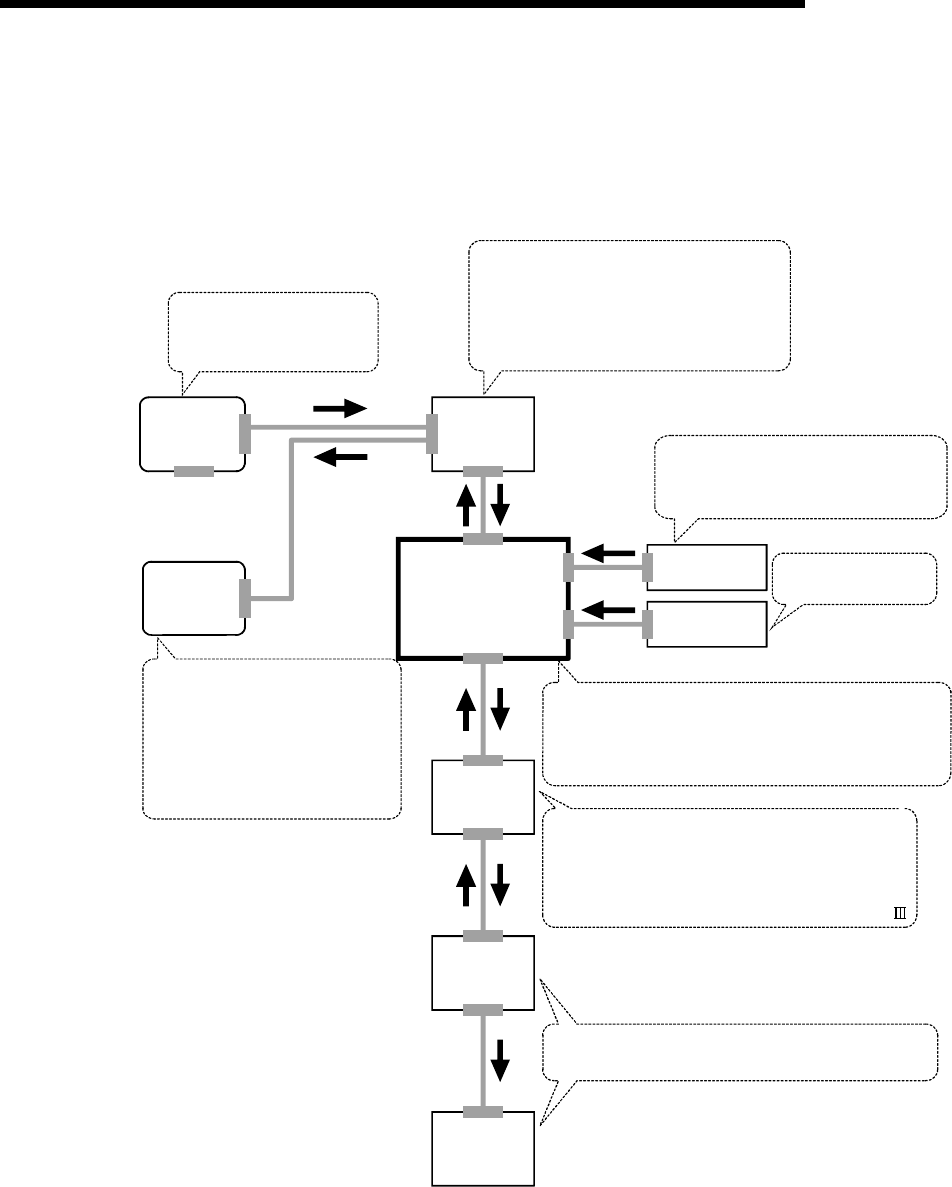
1.1.3 Mechanism of positioning control
In the positioning system using the QD75MH, various software and devices are used
for the following roles. The QD75MH realizes complicated positioning control when it
reads in various signals, parameters and data and is controlled with the PLC CPU.
Workpiece
Creates control order and
conditions as a sequence
program.
Stores the created program.
The QD75MH outputs the start signal and
stop signal following the stored program.
QD75MH errors, etc., are detected.
GX Developer
PLC CPU
Outputs signals such as the start
signal, forced stop input signal, stop
signal, limit signal and control
changeover signal to the QD75MH.
GX
Configurator
-QP
QD75MH positioning
module
External signal
Manual pulse
generator
Issues commands by
transmitting pulses.
Sets the parameters and
positioning data for control.
Outputs the start command for
JOG operation, etc., during test
operation with the test mode.
Monitors the positioning operation.
Servo
amplifier
Stores the parameter and data.
Outputs datas to the servo according to the
instructions from the PLC CPU, GX Configurator-QP,
external signals and manual pulse generator.
Receives positioning commands and control
commands from QD75MH, and drives the motor.
Outputs the positioning data of the motor
data and etc., and external input signal of the
servo amplifier to the QD75MH by the SSCNET .
Motor
Carries out the actual work according to commands
from the servo.
(Note): For QD75MH1, 2 and 4, use SW2D5C-QD75P (Version 2.21X) or later of the GX Configurator.